
Composite mold clamp building block

A composite mold and block technology, applied in building materials, building components, walls, etc., can solve the problems of inability to completely cut off thermal bridges, limited thickness of thermal insulation layers, and difficult to guarantee quality, and achieve good sound insulation and fast construction. , reduce the effect of construction materials

Inactive Publication Date: 2012-03-21
HUBEI SYNTHETIC SPACE TECH CO LTD
View PDF7 Cites 15 Cited by
  • Summary
  • Abstract
  • Description
  • Claims
  • Application Information

AI Technical Summary

Problems solved by technology

As the basic components, the inner molded block and the outer molded block are provided with vertical grouting channels, so the block itself is required to reach a certain thickness, coupled with the insulation layer between the inner and outer layers, the entire composite masonry The block is too thick; at the same time, because the vertical grouting holes and horizontal grouting grooves are set in the inner and outer layer mold blocks, the process requires grouting to ensure the stability of the wall, but after grouting, the wall has a large weight, so it is difficult to adapt Many, high-rise buildings need, and the construction is cumbersome, and the quality is difficult to guarantee
[0006] Second, the thickness of the insulation layer is limited
Since there are grouting through holes in the inner and outer molded blocks, they themselves have a certain thickness requirement. When the wall is required to be limited to a certain thickness in the design, it will cause the utility model If the insulation layer is too thin or even impossible to set, the insulation effect will be greatly reduced
[0007] Third, it is still impossible to completely cut off the thermal bridge

Method used


Image

  • Composite mold clamp building block
  • Composite mold clamp building block
  • Composite mold clamp building block

Examples


Embodiment Construction

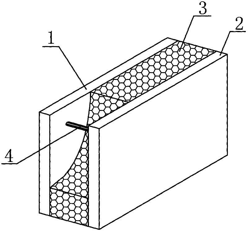
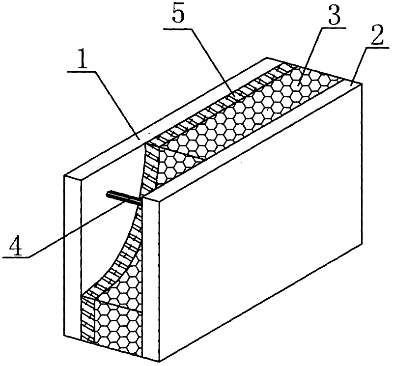
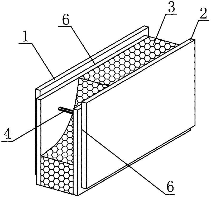
[0058] Below in conjunction with accompanying drawing, the present invention is further described: in each accompanying drawing, numbering is identical, and its description is identical. In the figure, 1 is the outer panel, 2 is the inner panel, 3 is the insulation layer, 4 is the connector, 5 is the heat insulation layer, 6 is the gap, 7 is the stiffener, 8 is the fixed support, 9 is the bump, and 10 is the Convex line, 11 is a concave hole, 12 is a pit, 13 is an embedded part, 14 is a hole, 15 is a groove, 16 is a connecting rod, 17 is a connecting piece, 18 is an injection hole, 19 is a movable hole cover, 20 for the insulation layer.

[0059] Such as figure 1 The composite molded block shown is characterized in that the composite molded block includes an outer panel 1 and an inner panel 2, and an insulating layer 3 is filled between the outer panel 1 and the inner panel 2, and the outer panel 1 and the inner panel 2 pass through The connecting piece 4 connects the outer ...


PUM


Abstract

A composite mold clamp building block is characterized by comprising an outer face plate (1) and an inner face plate (2). A heat preservation layer (3) is filled between the outer face plate (1) and the inner face plate (2). The outer face plate (1), the heat preservation layer (3) and the inner face plate (2) are connected to form a whole through connecting pieces (4). The composite mold clamp building block adopts an inner clamp heat preservation layer design, is lighter than a traditional clay brick, and meets the requirements of modern multiple floor buildings and high-rise buildings. A traditional process of on-site slurry wiping and wall building is changed, the building block can be directly installed and fixed, construction is fast, process flow and construction materials are reduced, and construction cost is lowered. After installation, the vertical face of a wall body is even and smooth, strength and rigidity of the vertical face are balanced. The composite mold clamp building block can effectively block heat bridge effect and obviously enhance heat preservation and insulation performance and fire-proof performance, and has good sound insulation effect and better comprehensive performance.

Description

technical field [0001] The invention relates to the technical field of construction, in particular to a composite molded block. Background technique [0002] With the rapid development of urban construction, it is the general trend for urban buildings to expand to many and high-rise buildings. However, the clay bricks used in traditional buildings have a large volume, resulting in a large building as a whole, and the formed walls have poor thermal insulation and sound insulation performance. Moreover, the production of this type of brick often destroys a large amount of farmland and damages water and soil conservation. The firing process of this type of brick also consumes a lot of energy, and its production has been restricted by the state. In order to adapt to the development of multi-story and high-rise buildings, it is necessary to develop composite wall materials with light weight, strong seismic performance, heat insulation, heat insulation, and sound insulation. [...

Claims


Application Information

Patent Timeline
Patent Type & Authority Applications(China)
IPC IPC(8): E04C1/40E04B2/08E04B2/18
Inventor 傅礼铭
Owner HUBEI SYNTHETIC SPACE TECH CO LTD
Learn More