Automatic gas diluter

A diluter and automatic technology, applied in the direction of gas discharge, safety devices, mining equipment, etc., can solve the problems of high cost and complex structure, and achieve the effects of low production cost, simple structure, good sealing and safety

Inactive Publication Date: 2014-09-03
HENAN POLYTECHNIC UNIV
View PDF4 Cites 0 Cited by
  • Summary
  • Abstract
  • Description
  • Claims
  • Application Information

AI Technical Summary

Problems solved by technology

In addition, with the continuous migration of the mining face, the position of the upper corner is also constantly changing. The existing processing method has a complex structure and high cost, and a small and portable ventilation mechanism is required to replace it.

Method used


Image

  • Automatic gas diluter
  • Automatic gas diluter
  • Automatic gas diluter

Examples


Embodiment 1

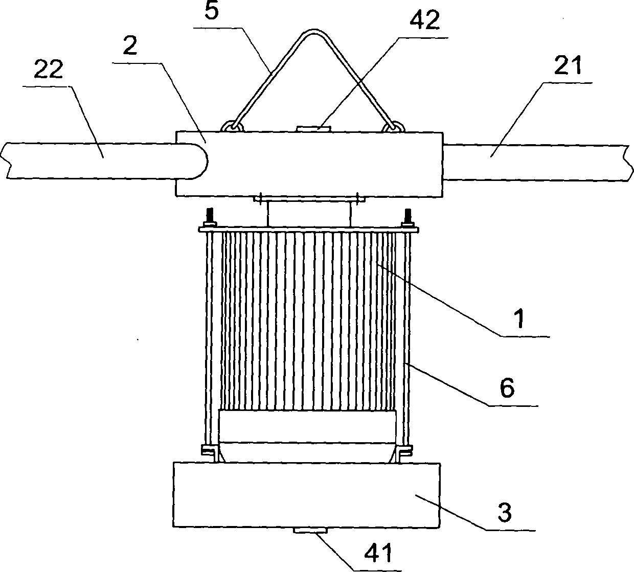
[0020] Embodiment one: see figure 1 , a gas automatic diluter, the fan includes a motor 1 and a wind turbine chamber 2. The output shaft of the motor 1 is connected to the turbine drive in the wind turbine chamber 2 upwards, and a hook 5 is arranged above the wind turbine chamber 2. After the top of the upper corner is punched and the hook is fixed, the hook 5 is hung on the hook. The lower part of the motor 1 is fixed with a battery casing 3 through a support rod 6, and a battery and a control circuit board are hermetically installed in the battery casing 3. Gas concentration sensors 41 and 42 are respectively installed on the battery casing 3 and the wind turbine chamber casing 2, the gas concentration sensor is sealed and connected to the input end of the control circuit board, the battery is sealed and connected to the control circuit board, and the output of the control circuit board The end is sealed with the motor input end. Motor 1 adopts explosion-proof motor.

Embodiment 2

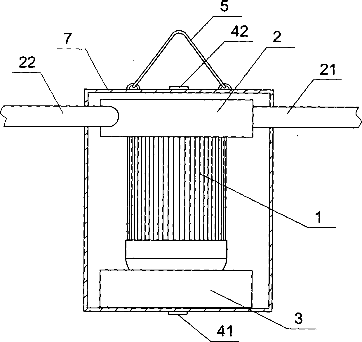
[0021] Embodiment two: see figure 2 , another gas automatic diluter, the content is basically the same as that of Embodiment 1, and the similarities will not be repeated. The difference is that it also includes an airtight support shell 7, and the battery, motor and wind turbine chamber are installed on the support In the casing, there may be multiple probes of the gas concentration sensor, which are respectively located on the side walls of the airtight casing. The upper part of the airtight casing is fixed with a buckle 5, and the air inlet pipe 21 and the air outlet pipe 22 of the wind turbine chamber are respectively fixed on the left and right side walls of the supporting casing. Due to the function of the airtight supporting shell, the motor can be an explosion-proof motor or an ordinary motor.

Embodiment 3

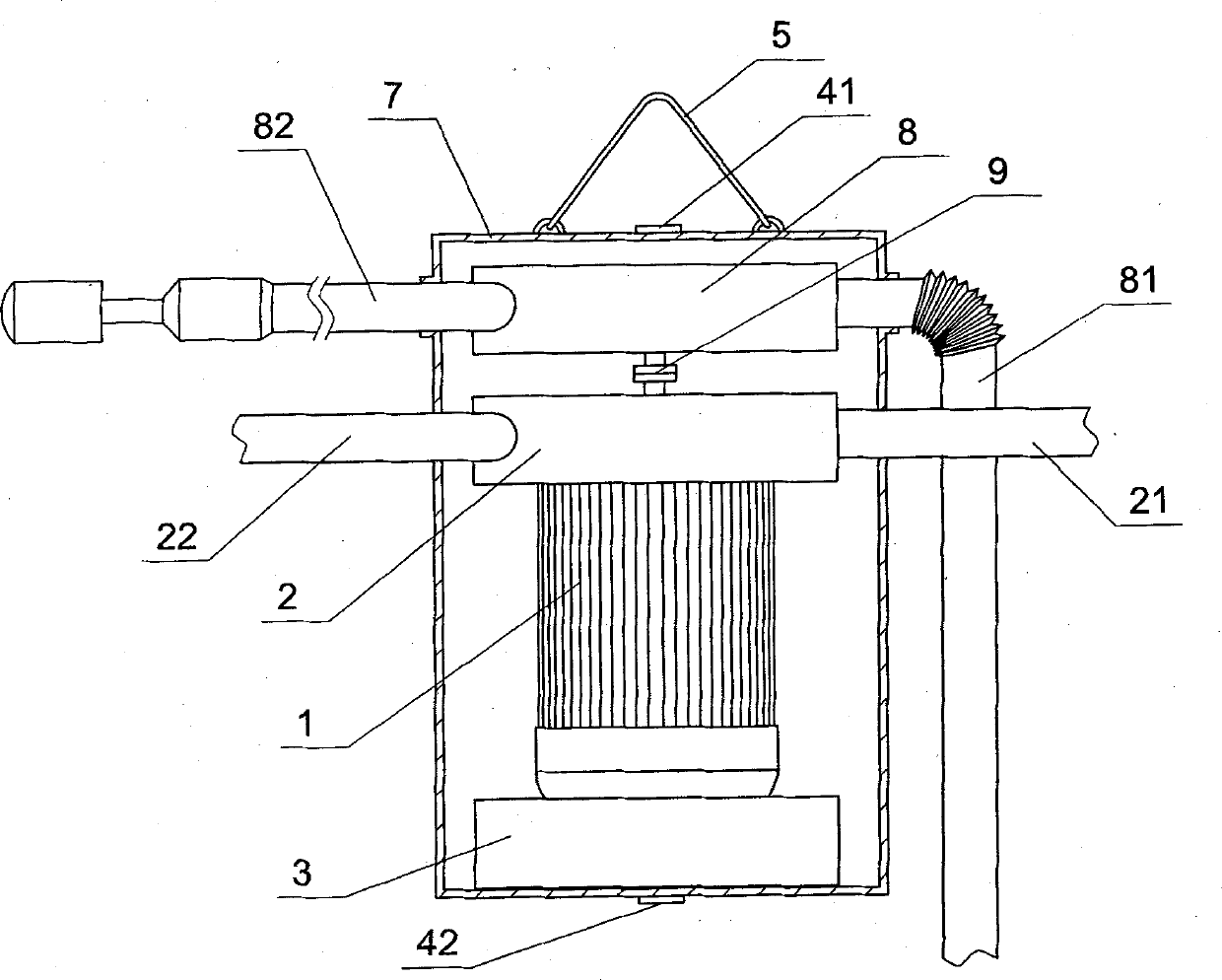
[0022] Embodiment three: see image 3 , another kind of gas automatic diluter, the content is basically the same as that of Embodiment 2, and the similarities will not be repeated. A water turbine chamber 8 is also arranged in the airtight support shell 7, and the output shaft of the motor is connected with the wind turbine chamber 2 and the water turbine chamber simultaneously. The turbine transmission in the turbine chamber 8 is connected, and the water inlet pipe 81 and the water outlet pipe 82 of the water turbine chamber 8 are respectively fixed on the side walls of the supporting shell, and the water inlet pipe can be communicated with the water container on the ground. In this embodiment, an electric clutch 9 is installed on the transmission shaft between the wind turbine chamber 2 and the water turbine chamber 8, and the signal line of the electric clutch 9 is sealed and connected with the output end of the control circuit board. The water outlet pipe 82 is a jet water...


PUM


Abstract

The invention relates to an automatic gas diluter. An output shaft of a motor is in transmission connection with a turbine in a wind turbine room upwards; a hanging buckle is arranged above the wind turbine room; a storage battery casing is fixed at the lower part of the motor; and gas concentration sensors are respectively installed on the storage battery casing and a wind turbine room casing. The automatic gas diluter is simple in structure, is easy to process and implement, has low production cost, is convenient to use, is portable and can move at any time along with the movement of an upper corner. The automatic gas diluter has the effects of automatic detection and automatic startup ventilation, is provided with a storage battery for providing the power and can hermetically treat each electrical contact, thereby being safe and practical and having good sealing performance and safety.

Description

Technical field: [0001] The invention relates to a gas dilution technology at the upper corner of a coal mining face, in particular to an automatic gas diluter. Background technique: [0002] During coal mining, due to the light density of gas, it is easy to gather in the upper corner of the mining face, and as the concentration increases, it is easy to reach the limit of explosion. At present, the commonly used methods for the problem of gas exceeding the limit in the upper corner are buried pipe drainage, local fans, and special tailgates, etc. These treatment methods are costly and practically complicated. In fact, the wind force at the mining face has been able to discharge a large amount of gas, and the upper corner is not easy to form air circulation, so the gas with a higher concentration gradually accumulates, and the gas treatment at the upper corner only needs to be taken according to its accumulated concentration. Circulation measures, because the local volume of...

Claims


Application Information

Patent Timeline
Patent Type & Authority Patents(China)
IPC IPC(8): E21F7/00E21F1/00
Inventor 彭信山戚灵灵雷东记李辉
Owner HENAN POLYTECHNIC UNIV
Why Eureka
Try Eureka