Hot air drying box

A technology of oven and hot air, which is applied in drying, drying machines, lighting and heating equipment, etc., and can solve the problem of high power consumption of the main suction air duct, increased suction force of the main shaft suction air duct, and the impact on non-woven fabrics. or cotton net heat drying effect and other issues, to achieve the effect of saving energy consumption and avoiding the phenomenon of yin and yang

Active Publication Date: 2012-03-21
常熟市伟成非织造成套设备有限公司
View PDF7 Cites 16 Cited by
  • Summary
  • Abstract
  • Description
  • Claims
  • Application Information

AI Technical Summary

Problems solved by technology

[0004] However, the above-mentioned CN201428045Y will show a yin and yang situation when the non-woven fabric or cotton net is heated. The heat-drying effect on the side of the main suction air duct is obviously better than that of the side facing the main suction air duct, thereby affecting the overall heat-drying effect of the non-woven fabric or cotton web; secondly, although the patent does not disclose the specific structure of the main air supply air duct, according to its The main suction air channel configured below shows that the high-temperature hot air from the main air supply channel is difficult to reflect the penetration ability of thicker non-woven fabrics or cotton nets, more specifically, the high-temperature hot air from the main air supply channel It is drawn out in the form of mist and does not have the effect of pressurization. It can only penetrate the non-woven fabric or cotton net under the relief of the equipped main suction air duct, and when the thickness of the non-woven fabric or cotton net is large, the main shaft The suction force of the suction duct increases accordingly, and the power consumption of the main suction duct is large, which is not conducive to energy saving

Method used


Image

  • Hot air drying box
  • Hot air drying box
  • Hot air drying box

Examples


Embodiment Construction

[0015] In order to enable the examiners of the patent office, especially the public, to understand the technical essence and beneficial effects of the present invention more clearly, the applicant will describe in detail the following in the form of examples, but none of the descriptions to the examples is an explanation of the solutions of the present invention. Any equivalent transformation made according to the concept of the present invention which is merely formal but not substantive shall be regarded as the scope of the technical solution of the present invention.

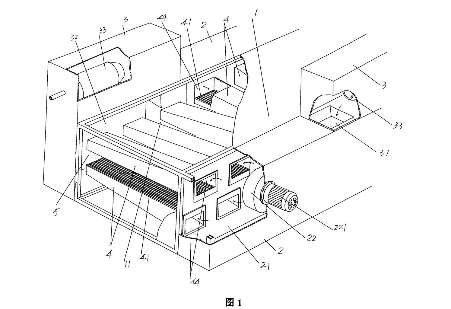
[0016] please see figure 1 , a box body 1 is given, the box body 1 is in the shape of a cuboid, and has a box body cavity 11 . shown in the figure and figure 1 Take the position shown as an example, a hot air chamber 2 and a combustion chamber 3 are formed (that is, installed) on one side of the length direction of the box body 1, that is, the right side shown in the figure, and the combustion chamber...


PUM


Abstract

The invention relates to a hot air drying box, and belongs to the technical field of nonwoven machines. The hot air drying box comprises a box body, a hot air chamber and a combustion chamber which are arranged on two sides of the box body and are provided with fans, and two groups of hot air lead-out pipes which are arranged in a box body cavity. The hot air drying box is characterized in that each group comprises the same number of hot air lead-out pipes which are arranged at intervals to form upper and lower rows; a fabric guiding cavity is formed between the hot air lead-out pipes on the upper and lower rows; air outlet channels positioned on the hot air lead-out pipes on the upper row are downward, air outlet channels positioned on the hot air lead-out pipes on the lower row are upward, and the adjacent air outlet channels are partitioned by air flue partition pipes; each air flue partition pipe is contracted gradually towards the direction of pipe cavities of the hot air lead-out pipes and forms a structure of which the cross section is in a trapezoidal shape; and the widths of the air outlet channels are reduced towards the direction away from the pipe cavities from the pipe cavities. The hot air drying box has the advantages that an ideal hot drying effect can be achieved, the non-uniform heating phenomenon is avoided, large-thickness nonwoven fabrics or cotton fleeces are easy to penetrate, and the consumption of energy is reduced.

Description

technical field [0001] The invention belongs to the technical field of non-woven machinery, and specifically relates to a hot air oven. Background technique [0002] The hot air oven is one of the indispensable equipment in the complete set of non-woven fabric production equipment or production line, which can be provided by the direct current processing device for paper and similar items disclosed in US patent US5052197 and the Chinese utility model patent authorization announcement number CN2286763Y The technical content of a non-woven fabric forming machine is understood in detail, and the structure of the hot air oven is described in detail in these two patents. However, these two patents are only suitable for processing thinner non-woven fabrics with a smaller grammage, and for non-woven fabrics with a grammage greater than 100g / ㎡ after needle punching and for laminating machines. The cotton web layer behind the net cannot be processed. [0003] The function of the ho...

Claims


Application Information

Patent Timeline
Patent Type & Authority Applications(China)
IPC IPC(8): F26B13/02F26B21/00
Inventor 王卫成
Owner 常熟市伟成非织造成套设备有限公司
Why Eureka
Try Eureka