
Stretching, compression and bending combined load mode material mechanics performance test device under microscope

A composite load, microscope technology, applied in the direction of using a stable bending force to test the strength of the material, using a stable tension/pressure test to test the strength of the material, etc. It can achieve the effect of wide range, good application development prospect and good structural compatibility.

Active Publication Date: 2012-03-21
JILIN UNIV
View PDF5 Cites 35 Cited by
  • Summary
  • Abstract
  • Description
  • Claims
  • Application Information

AI Technical Summary

Problems solved by technology

[0004] At the same time, in the existing composite load testing devices and research reports that can be used for in-situ observation, it is mainly for the testing of micro-scale components such as low-dimensional materials. If carbon nanotubes, wires or films with prefabricated gaps Materials, etc. The former needs to use complex methods such as scanning electron microscope imaging systems and focused ion beams to complete the clamping of micro devices, and is mostly based on complex processes such as micro-electromechanical systems (MEMS), while the latter mostly requires the use of substrate materials to realize sample clamping. The synthesis and growth of materials often require complex processes such as corrosion and deposition, and because the substrates used to attach thin film materials are often hard and brittle materials, it is difficult to clamp, so the mechanical tests on this material are mostly uniaxial compression tests , the test method is relatively simple
For the composite load test of three-dimensional specimens with characteristic sizes above centimeters, in-situ observation with the help of imaging instruments is not involved, and it is impossible to conduct in-depth research on the combination of composite loads, microscopic mechanical behavior of materials and degenerative damage processes

Method used


Image

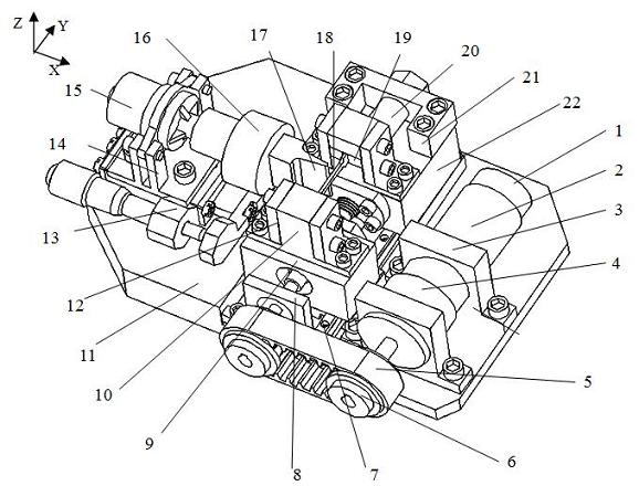
  • Stretching, compression and bending combined load mode material mechanics performance test device under microscope
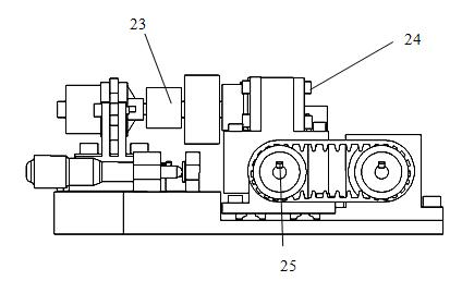
  • Stretching, compression and bending combined load mode material mechanics performance test device under microscope
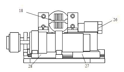
  • Stretching, compression and bending combined load mode material mechanics performance test device under microscope

Examples


Embodiment Construction

[0027] The detailed content of the present invention and its specific implementation will be further described below in conjunction with the accompanying drawings.

[0028] see Figure 1 to Figure 8 , the microscope pull-down compression-bending composite load mode material mechanical property testing device of the present invention includes a precise tensile / compressive load driving unit, a precise bending load driving unit, a clamping unit and a detection unit, and the precise tensile / compressive load driving unit Yes: DC servo motor 2 is connected to the transmission unit composed of reducer 4, synchronous belt 5, synchronous pulley 6 and precision ball screw 29, and DC servo motor 2 outputs precise angular displacement and controllable Torque, through the transmission unit composed of the reducer 4 connected to the DC servo motor 2, the synchronous belt 5 and the synchronous pulley 6, and the precision ball screw 29, the rotational motion provided by the DC servo motor 2 i...


PUM


Abstract

The invention relates to a stretching, compression and bending combined load mode material mechanics performance test device under a microscope, and belongs to the electromechanics. A test platform includes a precision stretching / compression load driving unit, a precision bending load driving unit, a clamping unit, a detecting unit and the like. The test platform can be used for the sole stretching / compression test, sole three-point bending test, and the stretching / compression-bending combined load test. The invention has the advantages that the structure is small and compact, and the tests can be performed under the real-time observation of the optical microscope; the loading mode of the combined load is in conformity with the stress state of material and members under the actual workingcondition, and combined with the optical microscopic imaging system, deepgoing study on the micromechanics behavior and denaturing impairment mechanism of the material under the action of combined load can be carried out.

Description

technical field [0001] The invention belongs to the electromechanical category, in particular to a device for testing the mechanical properties of materials in a microscope pull-down compression-bending composite load mode. It can be used independently as an independent tension / compression mode or three-point bending mode material performance testing device, and can also realize three-point bending tests at a given tension / compression stress level or tension / compression under a given bending stress state Test, that is, the composite load test mode. In addition, combined with high-resolution online monitoring of optical microscopic imaging, the micro-mechanical behavior and degenerative damage process of materials can be observed in real time. At the same time, through the closed-loop control of the drive unit and the collection of load / displacement signals, the stress-strain history of materials under compound loads can also be fitted, providing a method for testing the mech...

Claims


Application Information

Patent Timeline
IPC IPC(8): G01N3/16G01N3/20
Inventor 赵宏伟马志超李秦超王开厅胡晓利黄虎
Owner JILIN UNIV
Learn More