Vertically polarized broadband UHF (Ultra High Frequency) waveband antenna

A vertical polarization and antenna technology, which is applied in the direction of antenna, radiating element structure, radiating unit cover, etc., can solve the problems of small current balance reflection chassis, and can not meet the miniaturization installation requirements of UHF band communication system antenna.

Inactive Publication Date: 2012-03-21
NORTHWESTERN POLYTECHNICAL UNIV
View PDF5 Cites 3 Cited by
  • Summary
  • Abstract
  • Description
  • Claims
  • Application Information

AI Technical Summary

Problems solved by technology

[0003] In order to overcome the deficiency that the prior art cannot meet the miniaturized installation requirements of the UHF band communication system antenna on the high-speed mobile platform, the present invention provides a vertically polarized broadb...

Method used


Image

  • Vertically polarized broadband UHF (Ultra High Frequency) waveband antenna
  • Vertically polarized broadband UHF (Ultra High Frequency) waveband antenna
  • Vertically polarized broadband UHF (Ultra High Frequency) waveband antenna

Examples


Embodiment Construction

[0016] By continuously optimizing and adjusting the height of the active element, the distance between the two arms, the width of the arm, the distance between the active element and the reflective chassis, and the size of the reflective chassis, an antenna scheme that meets the requirements of standing waves and pattern can be obtained. The specific implementation methods are as follows:

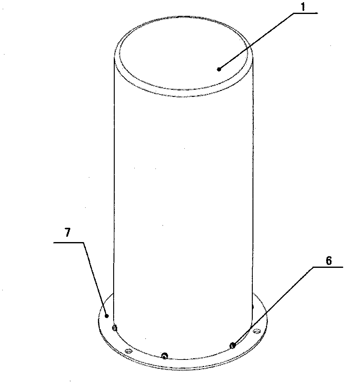
[0017] figure 1 It is a schematic diagram of the structure of the novel vertically polarized broadband UHF band antenna of the present invention. The radome 1 is made of epoxy laminated glass cloth with a thickness of 1 mm, the inner diameter of the radome is 80 mm, the outer diameter is 82 mm, and the height is 198 mm.

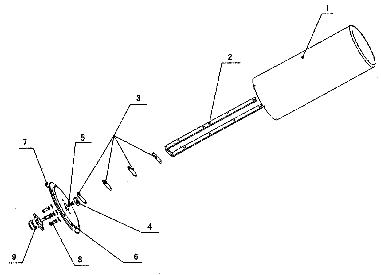
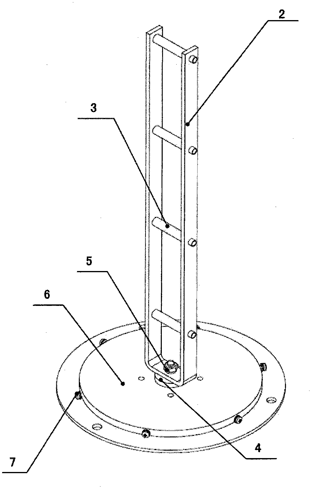
[0018] figure 2 , 3 It is the installation structure device and assembly schematic diagram of the novel vertically polarized broadband UHF band antenna of the present invention. 1.5 mm away from the bottom end of the radome 1, there are 6 positioning holes at equal int...


PUM


Abstract

The invention discloses a vertically polarized broadband UHF (Ultra High Frequency) waveband antenna. An antenna housing has a hollow cylindrical tubular structure, the upper end of the antenna housing is a sealing face, and the lower end is an opening; a reflecting base plate is a stepped cylinder of which the center is provided with a through hole; an insulating spacer is placed in the through hole; an active array has a U-shaped structure which is integrally formed by bending a rectangular aluminum rod; the two edges of the U-shaped structure are symmetrically distributed, and the top end is an open part; the active array is perpendicular to the upper surface of the reflecting base plate; an inner conductor of a radio frequency connecting piece penetrates through the insulating spacer to be fixedly connected with a mounting through hole on the bottom of the active array; the metal aluminum is made into a cylindrical short-circuit rod to be mounted at through holes on two arms of the active array; and a 50-ohm copper shaft cable is connected with the antenna by the radio frequency connecting piece. In the invention, the antenna meets requirements of vertical polarization and omnidirectional radiation; antenna gain reaches 2dB; 3dB beam width of the antenna is 65 degrees; and the width of frequency band below standing wave 2 is about 20 percent.

Description

technical field [0001] The invention relates to a broadband UHF band antenna. Background technique [0002] At present, the UHF band communication and measurement and control system antennas on general vehicle-mounted, airborne and other portable high-speed mobile platforms are mostly "J"-shaped dipole or disc-cone antennas. The "J" type dipole antenna uses the three-quarter wavelength main element as the basic radiation unit of the antenna, and introduces a quarter-wavelength matching element structure next to the main element to complete the matching between the overall system and the 50-ohm feed. According to the ordinary dipole matching mode, W.B. Freely first proposed the design of the antenna in the article "A Two meter J Antenna" (W.B. Freely, A Two meter J Antenna [J] QST, April, 1977). The "J" type dipole antenna has the characteristics of simple structure and easy tuning, but it often has a narrow operating frequency band (less than 5%). Generally, it works at a p...

Claims


Application Information

Patent Timeline
IPC IPC(8): H01Q1/36H01Q1/42H01Q15/14H01Q19/10
Inventor 张朋刘春阳袁俊刘亚成
Owner NORTHWESTERN POLYTECHNICAL UNIV
Why Eureka
Try Eureka