
Pressurizing dust remover of gasoline engine

A technology for dust collectors and gasoline engines, which is applied to machines/engines, mechanical equipment, engine components, etc., and can solve problems such as fuel increase, temperature engine performance wear, displacement power, and functions that do not meet design requirements.

Inactive Publication Date: 2012-03-28
尚玉东
View PDF5 Cites 1 Cited by
  • Summary
  • Abstract
  • Description
  • Claims
  • Application Information

AI Technical Summary

Problems solved by technology

With the air filter of the intake system, the bend of the intake pipe, the high and low temperature, the wear and tear of the engine performance, and the invisible increase of fuel, the original displacement, power and function cannot meet the design requirements

Method used


Image

  • Pressurizing dust remover of gasoline engine
  • Pressurizing dust remover of gasoline engine
  • Pressurizing dust remover of gasoline engine

Examples


Embodiment Construction

[0010] specific implementation plan

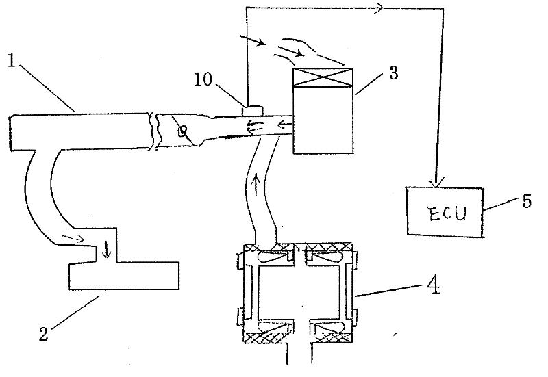
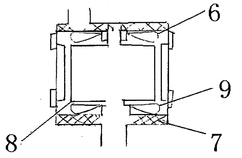
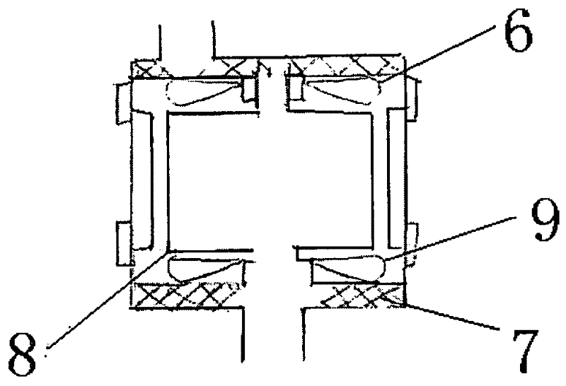
[0011] During actual use, according to the arrangement of the engine, the supercharger dust collector 4 is arranged on the side of the intake pipe 1, so that the air volume of the supercharger 4 is included in the air flow meter for measurement. The power supply of the dust collector is controlled ON-OFF by the ignition switch, and the body of the pressurized dust collector 4 is designed to be connected up and down, which is convenient for cleaning and maintenance.


PUM


Abstract

The invention relates to automobile engine power engineering, aerodynamics, mechanical and electric integration, fuel electric injecting system, maintaining engineering, energy conservation and exhaustion reduction, belonging to the automobile mechanical engineering. In accordance with aerodynamics relay principle, an upright direct-current high revolving speed motor is designed as the basis, coaxial relaying fans are arranged at the top and bottom of a rotor, and rotated together to carry out air absorbing and exhausting in the same direction; different exhaustion rates of the engine are corresponding to different pressurizing dust removers; the air quality, temperature, and opening degree of the throttle valve are kept reasonable; when the burning pressure is fixed, the injecting rate is reduced, the energy conservation and exhaustion reducing are achieved.

Description

Technical field: [0001] The invention relates to automobile engine power engineering, aerodynamics, mechatronics, fuel electronic control injection system, maintenance engineering, energy saving and emission reduction, and belongs to automobile mechanical engineering. Background technique: [0002] Existing gasoline engine intake air volume and mixed gas all rely on piston to continuously circulate intake air work. With the air filter of the intake system, the bend of the intake pipe, the high and low temperature, the wear and tear of the engine performance, and the invisible increase of fuel, the original displacement, power and function cannot meet the design requirements. Invention content: [0003] Based on the worldwide requirements for energy saving and emission reduction, the present invention designs a gasoline engine air intake flow relay pressurized dust collector based on the original electronic injection system, which increases the fresh air flow rate, makes th...

Claims


Application Information

Patent Timeline
IPC IPC(8): F02M35/024F02B33/40
Inventor 尚玉东
Owner 尚玉东
Learn More