Cotton temperature and humidity data automation acquisition and monitoring equipment and method thereof

A technology of automatic collection and monitoring equipment, which is applied in the direction of measuring devices, instruments, signal transmission systems, etc., can solve the problems of low data accuracy and inconvenient monitoring, and achieve the effect of realizing benefits, facilitating decision-making management, and facilitating decision-making management

Inactive Publication Date: 2012-03-28
SHIHEZI UNIVERSITY
1 Cites 8 Cited by

AI-Extracted Technical Summary

Problems solved by technology

[0005] The purpose of the present invention is to provide an automatic acquisition and monitoring device for temperature and humidity data of cotton piles that can effectively ...

Abstract

The invention discloses cotton temperature and humidity data automation acquisition and monitoring equipment which comprises a control host (15). The equipment is characterized in that: the equipment mainly comprises three function modules: a temperature and humidity acquisition module, a wireless data emission module and a wireless data receiving module. The invention also discloses a cotton temperature and humidity data automation acquisition and monitoring method. The method mainly comprises the following steps: arranging required hardware apparatuses; executing main control program; reading data and controlling a subprogram; executing a monitoring program; executing a query program and an early warning program. In the invention, wireless sensing and a computer expert decision management technology are integrated; temperature and humidity change situations of the cotton can be dynamically monitored so that a manger can decide and manage conveniently; mildew generation caused by stacking for a long time can be reduced and avoided; postharvest losses can be reduced and a usage value of seed cotton resources can be raised; maximization of seed cotton benefits can be realized; costs can be substantially saved during a usage process; the equipment and the method are convenient to use.

Application Domain

Measurement devicesTransmission systems

Technology Topic

Execution controlDecision management +10

Image

  • Cotton temperature and humidity data automation acquisition and monitoring equipment and method thereof
  • Cotton temperature and humidity data automation acquisition and monitoring equipment and method thereof
  • Cotton temperature and humidity data automation acquisition and monitoring equipment and method thereof

Examples

  • Experimental program(2)

Example Embodiment

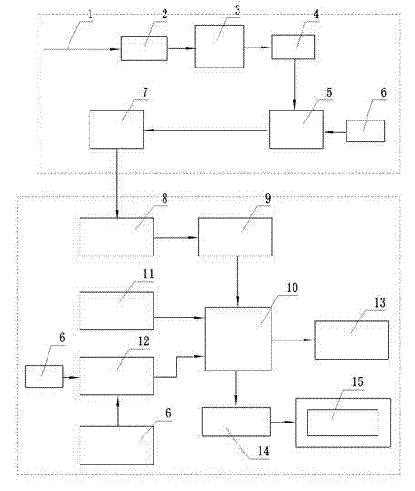
[0045] Embodiment 1: Referring to the appended figure 1 , a cotton stack temperature and humidity data automatic collection and monitoring equipment, including a control host 15, is characterized in that it also mainly includes three functional modules:
[0046] (1) Temperature and humidity acquisition module: mainly includes temperature and humidity sensor 2, microprocessor MCUⅠ4, analog signal amplifier 3;
[0047] (2) Wireless data transmission module: mainly includes wireless data transmission chip 5, wireless data transmission antenna 7, power-down backup battery 6;
[0048] (3) Wireless data receiving module: mainly includes microprocessor MCUⅡ10, clock chip 11, data storage chip 13, power management chip 12, power-down backup battery 6, wireless data receiving chip 9 and wireless data receiving antenna 8, the data The receiving antenna 8 is connected to the wireless data receiving chip 9, and the microprocessor MCUII10 is connected to the control host 15 through the communication port;
[0049] The temperature and humidity acquisition module is placed in a metal shell with air holes, the temperature and humidity acquisition module is connected to the wireless data transmitting module through a data line, and the wireless data receiving module is connected to the control host 15 through a communication port.
[0050] The temperature and humidity acquisition modules are placed in the cotton pile, and there are three groups in quantity, which are respectively arranged in three different positions of the upper layer, the middle layer and the lower layer of the cotton pile. These three groups of temperature and humidity acquisition modules are all connected by communication data lines.
[0051] The temperature and humidity sensor 2 in the temperature and humidity acquisition module adopts a digital temperature and humidity sensor, and the outside of each group of temperature and humidity acquisition modules is equipped with a shell with air holes on three sides made of steel materials. The signal output terminal is connected with the microprocessor MCUⅠ4 through the analog signal amplifier 3, the signal input terminal of the wireless data transmitting chip 5 is connected with the microprocessor MCUⅠ4 of the temperature and humidity acquisition module, and the output terminal of the wireless data receiving chip 9 is connected with the wireless data receiving module. The microprocessor MCUⅡ10 of the module is connected.
[0052] The wireless data transmitting module is placed outside the cotton stack, and is connected with the temperature and humidity acquisition module placed in the cotton stack through a shielded wire, and the wireless data transmitting antenna 7 is connected with the wireless data transmitting chip 5 by a communication line. The position of the wireless data transmitting antenna 7 is not fixed, and can be placed in different positions according to the actual line layout. The shielded wire is a shielded cable protected by a metal threaded pipe.
[0053] The signal output end of the clock chip 11 and the signal output end of the power management chip 12 are all connected with the microprocessor MCU II 10 of the wireless data receiving module, and the microprocessor MCU II 10 of the wireless data receiving module communicates with the control via the RS232/USB port 14 Host 15 is connected.

Example Embodiment

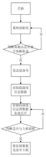
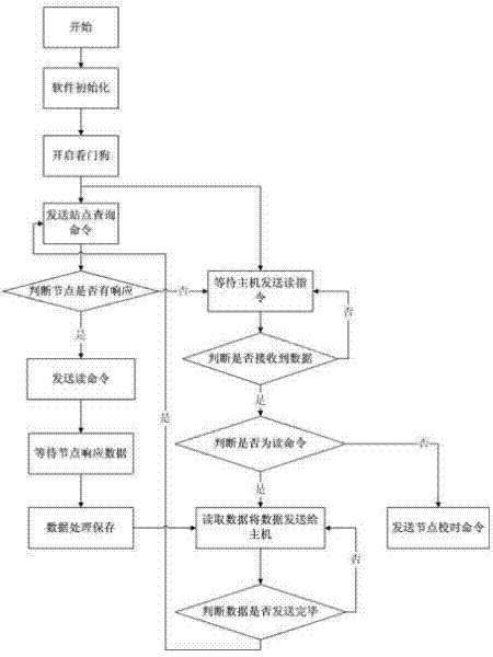
[0054] Embodiment 2: Referring to the attached Figure 1-Figure 6 , a method for automatically collecting and monitoring temperature and humidity data of cotton stacks, mainly comprising the following steps:
[0055] (1) Arranging the required hardware devices:
[0056] (1), the control host 15 storing the control main program;
[0057] (2) The temperature and humidity acquisition module placed in the cotton pile to be monitored: including temperature and humidity sensor 2, microprocessor MCU Ⅰ 4, and analog signal amplifier 3;
[0058] (3) The wireless data transmitting module placed outside the cotton stack to be monitored: including the wireless data transmitting chip 5, the wireless data transmitting antenna 7, and the power-down backup battery 6;
[0059] (4) Wireless data receiving module: mainly includes microprocessor MCUⅡ10, clock chip 11, data storage chip 13, power management chip 12, power-down backup battery 6, wireless data receiving chip 9 and wireless data receiving antenna 8, the data The receiving antenna 8 is connected to the wireless data receiving chip 9, and the microprocessor MCUII10 is connected to the control host 15 through the communication port;
[0060] The temperature and humidity acquisition module is placed in a metal shell with air holes, the temperature and humidity acquisition module is connected to the wireless data transmitting module through a data line, and the wireless data receiving module is connected to the control host 15 through a communication port;
[0061] (2) The main control program is stored in the control host 15, and the control subroutine is stored in the microprocessor MCUII. The control process mainly includes the following steps:
[0062] (1) Execute the main control program: system initialization, set temperature and humidity alarm values, and send commands to read temperature and humidity data to the wireless data receiving module; see figure 2 Control main program flow chart: system initialization, judging whether the monitoring point, that is, the connection and working status of each group of temperature and humidity acquisition modules is normal, if the connection is normal and the working status is normal, that is, send the command to read the temperature and humidity signal, and store the temperature and humidity signal after reading it normally In the data storage chip, if the connection with the control host is normal, the information data will be sent to the host;
[0063] (2) Data reading and control: The temperature and humidity sensor 2 responds to the collection instructions of the wireless data receiving module, and collects the temperature and humidity information of the cotton pile monitoring point where the temperature and humidity sensor 2 is located in real time, and the collected temperature and humidity information After being processed by the microprocessor MCUⅠ4, it is transmitted to the wireless data transmitting chip 5, and the data signal is sent through the wireless data transmitting antenna 7; the data is transmitted to the wireless data receiving chip 9 through the wireless data receiving antenna 8, and the microprocessor MCUⅡ10 analyzes and processes the received data. Cotton stack temperature and humidity information data and the information data are transmitted to the control host 15; referring to the control subroutine flow chart: system initialization, sending site query command, judging whether the monitoring point is that each group of temperature and humidity acquisition modules is connected to the working state normally, if normal, Then send the command to read the temperature and humidity data, and read the data and send the data to the control host; if it is abnormal and there is no response, wait for the control host to send a read command to determine whether it is a read command, if yes, read the data and send it to the control host. Data is sent to the control host. If it is judged in the previous step that it is not a read command, then send a node timeout command.
[0064] (3) Execute the monitoring program: the chart shows the time, temperature and humidity waveform; see Figure 4 The flow chart of the monitoring subroutine shown: judge whether it is correctly connected to the lower computer, if it is connected correctly, start monitoring, read the current time, read the temperature and humidity data, calculate the temperature percentage and humidity percentage, the chart shows the time, Temperature and humidity percentage waveform, store the time, temperature percentage, and humidity percentage in the database, judge whether to stop monitoring, if yes, the program ends, if not, return to start monitoring again.
[0065] (4) Execute query program: display query history results; see Figure 5 The flow chart of the query subroutine shown: establish a database connection, refresh the database, then set the query time period, obtain the query data source, judge whether it is within the set time, if not, reset the query time, if yes , then display the time, temperature and humidity percentage in the table, judge whether to traverse the time in the database, if yes, end the query, otherwise return to the previous section to query the time again.
[0066] (5) If the collected temperature and humidity values ​​reach or exceed the alarm value, execute the early warning procedure. see Image 6 The flow chart of the alarm subroutine shown: start, send the alarm value query command, judge whether the alarm value is exceeded, if not, resend the alarm query command, if yes, alarm.
[0067] The temperature and humidity acquisition modules in the hardware device required for the above (1) layout are placed in the cotton pile, and the number is four groups, which are respectively arranged in three different positions of the upper layer, the middle layer, and the lower layer of the cotton pile. The four groups of temperature and humidity acquisition modules The modules are connected through communication data lines.
[0068]The temperature and humidity sensor 2 in the temperature and humidity acquisition module adopts a digital temperature and humidity sensor, and the outside of each group of temperature and humidity acquisition modules is equipped with a shell with air holes on three sides made of steel materials. The signal output terminal is connected with the microprocessor MCUⅠ4 through the analog signal amplifier 3, the signal input terminal of the wireless data transmitting chip 5 is connected with the microprocessor MCUⅠ4 of the temperature and humidity acquisition module, and the output terminal of the wireless data receiving chip 9 is connected with the wireless data receiving module. The microprocessor MCUⅡ10 of the module is connected.
[0069] The wireless data transmitting module is placed outside the cotton stack, and is connected with the temperature and humidity acquisition module placed in the cotton stack through a shielded wire, and the wireless data transmitting antenna 7 is connected with the wireless data transmitting chip 5 by a communication line. The position of the wireless data transmitting antenna 7 is not fixed. The signal output end of the clock chip 11 and the signal output end of the power management chip 12 are all connected with the microprocessor MCU II 10 of the wireless data receiving module, and the microprocessor MCU II 10 of the wireless data receiving module communicates with the control via the RS232/USB port 14 Host 15 is connected.

PUM

no PUM

Description & Claims & Application Information

We can also present the details of the Description, Claims and Application information to help users get a comprehensive understanding of the technical details of the patent, such as background art, summary of invention, brief description of drawings, description of embodiments, and other original content. On the other hand, users can also determine the specific scope of protection of the technology through the list of claims; as well as understand the changes in the life cycle of the technology with the presentation of the patent timeline. Login to view more.

Similar technology patents

Swinging spinning and winding noodle extension machine

Owner:巴彦淖尔市冠生园食品有限责任公司

Petroleum pipeline conveying device

Owner:江苏赛弗道管道股份有限公司

Classification and recommendation of technical efficacy words

  • labor saving

Organic ecological farming system for rice field

InactiveCN105532342Alabor savingrealization cost
Owner:HUAIAN SUZE ECOLOGICAL AGRI CO

Spring loading device of limiting switch assembling machine

Owner:SUZHOU ISHIMARU ERI PML PRECISION MECHANISM CO LTD

Automatic piece counting method and system for machining workshop of numerically-controlled machine tool

InactiveCN105334798AAccurate information collectionlabor saving
Owner:HUAZHONG UNIV OF SCI & TECH

Multi-coin sorting and packing device

InactiveCN105976500AHigh precisionlabor saving
Owner:SHANGHAI UNIV OF ENG SCI
Why Eureka
Try Eureka