
X-ray machine imaging device based on automatic diaphragm control

A technology for an X-ray machine and an imaging device, applied in the field of imaging devices, can solve the problems of high requirements for technicians, deteriorating imaging quality, and heavy debugging workload, and achieve the effects of accurate driving position, fast driving speed and good linearity

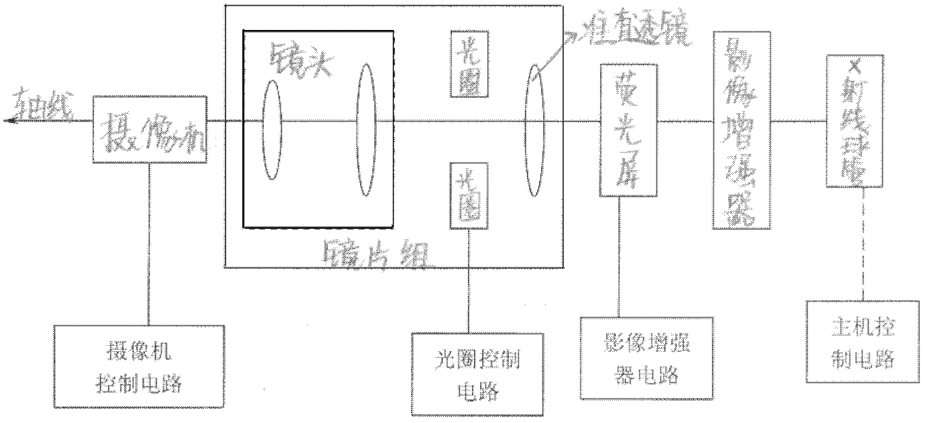
Inactive Publication Date: 2013-07-31
BEIJING DONGJIAN YUXING TECH
View PDF5 Cites 0 Cited by
  • Summary
  • Abstract
  • Description
  • Claims
  • Application Information

AI Technical Summary

Problems solved by technology

[0012] 1) Due to the separation of lens groups, the workload of debugging is relatively large, and the requirements for technical personnel are relatively high
[0013] 2) Long-term use is easy to deviate, resulting in deterioration of imaging quality
[0014] 3) Higher cost
[0017] Adopting such a scheme can ensure the image quality, but the aperture control becomes a difficult problem, because in this field, there is no convenient, high-precision, and low-cost control method. Many manufacturers use magnets, levers, etc. The method is just a solution, but it cannot fully meet the requirements of use

Method used


Image

  • X-ray machine imaging device based on automatic diaphragm control
  • X-ray machine imaging device based on automatic diaphragm control
  • X-ray machine imaging device based on automatic diaphragm control

Examples


Embodiment Construction

[0031] The technical solutions of the present invention will be described in further detail below in conjunction with the accompanying drawings and specific embodiments.

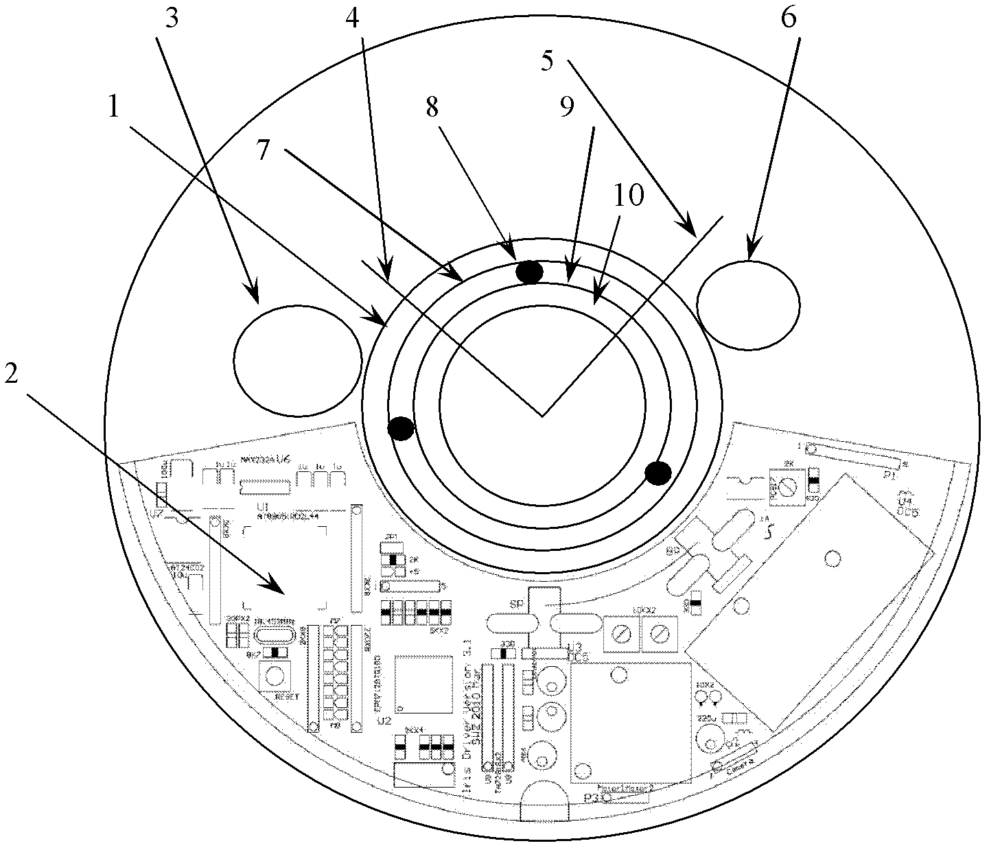
[0032] like image 3 as shown, image 3 It is a side view of an X-ray machine imaging device based on automatic aperture control proposed by the present invention. from image 3 It can be seen that the device includes an aperture positioning ruler 1, a driving circuit 2, a dimming film driving motor 3, a first aperture limit point 4, a second aperture limit point 5, an aperture drive motor 6, a rolling bearing 7, and a flexible coupling 8, Aperture drive ring 9, high resolution manual lens 10 and circumference counter 11.

[0033] Keeping the aperture drive system coaxial with the high-resolution manual lens 10 during assembly is the key to ensure the smooth operation of the system. The assembly error of the current system cannot meet the long-term work and use of the lens. Therefore, between the aperture...


PUM


Abstract

The invention relates to an X-ray machine imaging device based on automatic diaphragm control, which is characterized by comprising a diaphragm driving motor, a high-resolution manual lens, a diaphragm positioning rule, a diaphragm driving ring and a diaphragm motion control unit, wherein the diaphragm motion control unit comprises a main controller, a memory, a logic control circuit, a circumference counter, a first limit point, a second limit point and a motor driving circuit; the main controller is connected with the memory; the logic control circuit is connected with the main controller, the circumference counter, the first limit point, the second limit point and the motor driving circuit; the motor driving circuit is connected with the diaphragm driving motor; the diaphragm driving motor is connected with a diaphragm of the high-resolution manual lens, the diaphragm driving ring and the diaphragm motion control unit; and the diaphragm positioning rule is arranged on the high-resolution manual lens and connected with the circumference counter.

Description

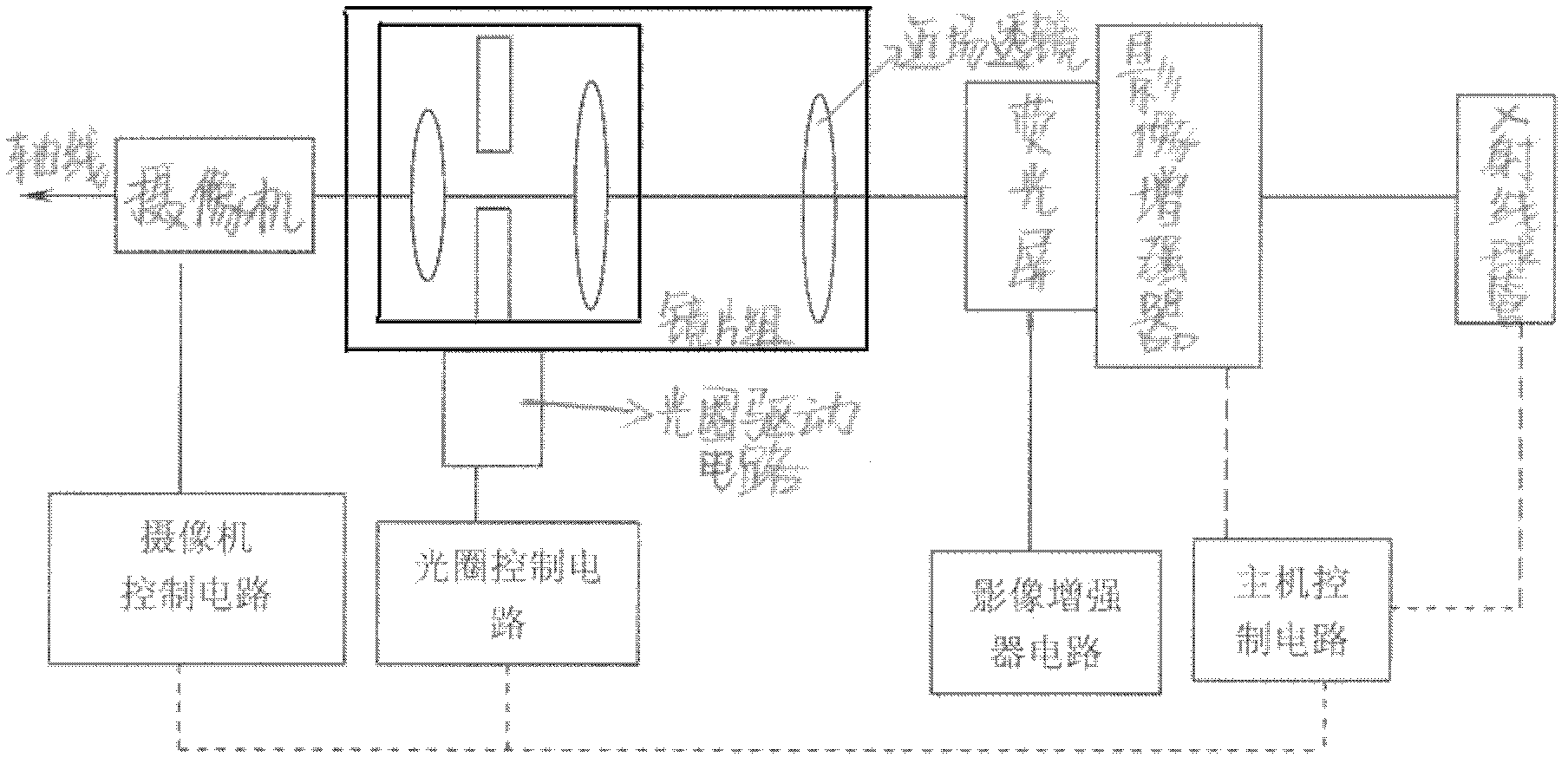
technical field [0001] The invention relates to an imaging device, in particular to an X-ray machine imaging device based on automatic aperture control. Background technique [0002] The main structure adopted by the aperture of the medical X-ray machine imaging system at present: [0003] The main structure adopted is mainly adopted by Siemens and Toshiba, such as figure 1 as shown, figure 1 It is a structural schematic diagram of an X-ray machine imaging device whose lens is composed of a group of mirrors. The dotted line in the figure indicates the internal wiring of the device. Its main features are: [0004] 1. The aperture system is separated from the lens system [0005] The so-called separation of the aperture system and the lens system means that the lens is composed of a group of lens groups, the aperture is between the lens groups, and the lens groups need to be adjusted during installation. The image quality has a great relationship with the installation. ...

Claims


Application Information

Patent Timeline
Patent Type & Authority Patents(China)
IPC IPC(8): G03B42/02H04N5/232
Inventor 金兆龙樊明山孙卫真
Owner BEIJING DONGJIAN YUXING TECH
Learn More