
Automatic plane polishing device

An automatic polishing and transmission technology, applied in surface polishing machine tools, grinding/polishing equipment, metal processing equipment, etc., can solve the problems of backward equipment, poor quality, low production efficiency, etc. High production efficiency and good polishing effect

Inactive Publication Date: 2012-04-04
SHENYANG LIGONG UNIV
View PDF6 Cites 3 Cited by
  • Summary
  • Abstract
  • Description
  • Claims
  • Application Information

AI Technical Summary

Problems solved by technology

[0002] At present, in the field of small surface polishing such as sign lighting, it is generally used to polish small surface parts manually, which has poor quality, low production efficiency, and backward equipment. In order to complete the polishing process efficiently, equipment with a high degree of automation is urgently needed

Method used


Image

  • Automatic plane polishing device
  • Automatic plane polishing device
  • Automatic plane polishing device

Examples


Embodiment 1

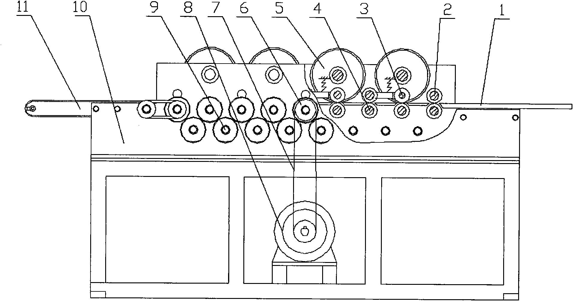
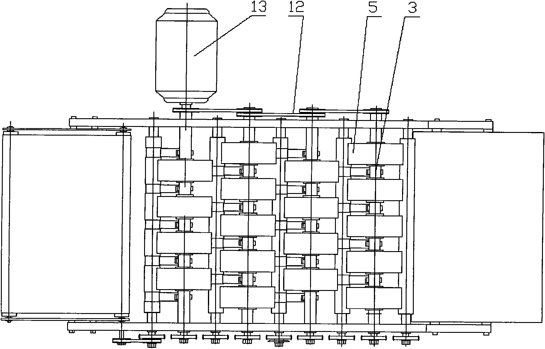
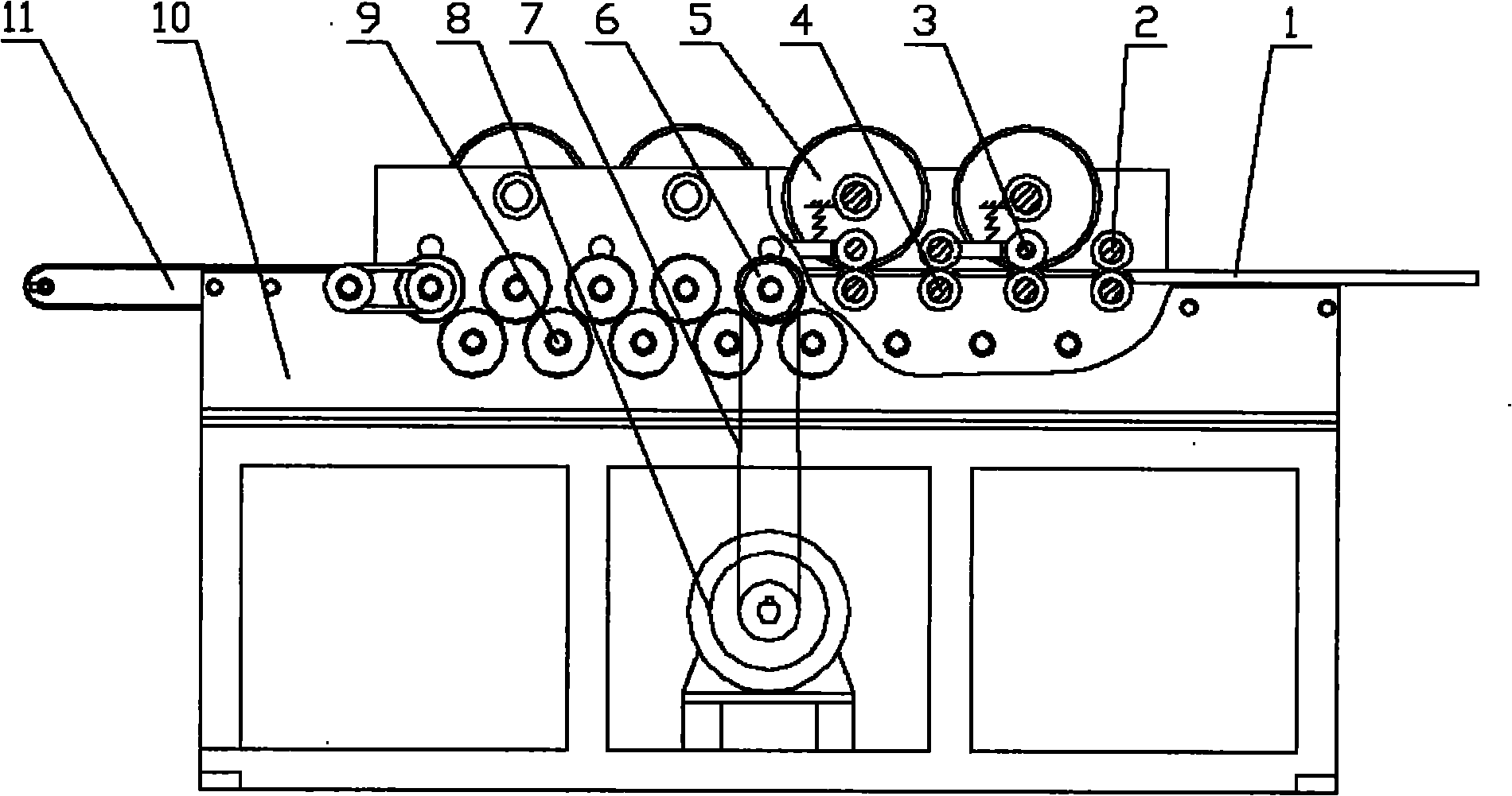
[0011] This embodiment provides a flat automatic polishing device, including a feeding table 1, a pressure roller 2, a point pressure roller 3, a driving roller 4, a polishing wheel 5, a sprocket 6, a transmission chain 7, a feed motor 8, a Gear 9, frame 10, blanking device 11, transmission device 12, polishing motor 13;

[0012] Among them: the feeding table 1 is installed on the frame 10, the feed motor 8 is installed on the frame 10, the pressure roller 2 and the driving roller 4 are pressed and installed on the frame 10, and the feed motor 8 passes through the transmission chain 7 and sprocket wheel 6 are connected with driving roller 4, and driving roller 4 is connected with reversing gear 9 through gear, and polishing wheel 5 is connected with polishing motor 13 through transmission device 12, and unloading device 11 is installed on the loading table 1. The point pressure roller 3 is hingedly mounted on the shaft of the polishing wheel 5 through a connecting rod, and the...

Embodiment 2

[0016] This embodiment provides a flat automatic polishing device, including a feeding table 1, a pressure roller 2, a point pressure roller 3, a driving roller 4, a polishing wheel 5, a sprocket 6, a transmission chain 7, a feed motor 8, a Gear 9, frame 10, blanking device 11, transmission device 12, polishing motor 13;

[0017] Among them: the feeding table 1 is installed on the frame 10, the feed motor 8 is installed on the frame 10, the pressure roller 2 and the driving roller 4 are pressed and installed on the frame 10, and the feed motor 8 passes through the transmission chain 7 and sprocket wheel 6 are connected with driving roller 4, and driving roller 4 is connected with reversing gear 9 through gear, and polishing wheel 5 is connected with polishing motor 13 through transmission device 12, and unloading device 11 is installed on the loading platform 1. The point pressure roller 3 is hingedly mounted on the shaft of the polishing wheel 5 through a connecting rod, and ...


PUM


Abstract

The invention discloses an automatic plane polishing device. The automatic plane polishing device comprises a feed platform, compression rollers, point compression rollers, driving rollers, polishing wheels, a chain wheel, a transmission chain, a feed motor, reversing gears, a rack, a discharging device, a transmission device and a polishing motor; the feed platform and the feed motor are arranged on the rack, the compression roller and the driving rollers are compacted and arranged on the rack, the feed motor is connected with the driving rollers through the transmission chain and the chain wheel, the driving rollers are connected with the reversing gears through gears, the polishing wheels are connected with the polishing motor through the transmission device, and the discharging device is arranged on the feed platform, and the point compression rollers are hinged on shafts of the polishing wheels through connecting rods which are arranged on the rack through a compressed spring, the polishing wheels are sequentially distributed in a staggered way in a feed direction, and the point compression rollers are sequentially distributed in a staggered way in the feed direction. The automatic plane polishing device has a good polishing effect, and is simple in a principle and a structure, and high in production efficiency and convenient to manufacture and use; and the process cost is far lower than that of the conventional manual polishing mode.

Description

technical field [0001] The invention relates to the field of plane polishing equipment, and particularly designs an automatic plane polishing device. Background technique [0002] At present, in the field of small surface polishing such as sign lighting, it is generally used to polish small surface parts manually, which has poor quality, low production efficiency, and backward equipment. In order to complete the polishing process efficiently, equipment with a high degree of automation is urgently needed. Contents of the invention [0003] The object of the present invention is to realize the automatic polishing device of the facet, and especially provides a flat automatic polishing device. [0004] The invention provides a plane automatic polishing device, which includes a feeding table, a pressure roller, a point pressure roller, a driving roller, a polishing wheel, a sprocket, a transmission chain, a feed motor, a reversing gear, a frame, and a feeding device , a transm...

Claims


Application Information

Patent Timeline
Patent Type & Authority Applications(China)
IPC IPC(8): B24B29/02
Inventor 张海龙郭虹
Owner SHENYANG LIGONG UNIV
Learn More