Burner used for gasifier

A gasification furnace and gasification agent channel technology, applied in the direction of granular/powdered fuel gasification, injection device, liquid injection device, etc., can solve the problem of increasing the complexity, danger, and poor cooling effect of the gasification furnace operation program , increase operating time and other issues, to avoid dew point corrosion and high temperature creep conditions, facilitate production and installation, and avoid high temperature damage

Active Publication Date: 2014-04-02
DONGFANG BOILER GROUP OF DONGFANG ELECTRIC CORP
View PDF4 Cites 0 Cited by
  • Summary
  • Abstract
  • Description
  • Claims
  • Application Information

AI Technical Summary

Problems solved by technology

[0022] Its disadvantages are: due to the addition of a layer of cooling water outer tubes and cooling water atomization tubes connected to the outer cooling water tubes on the outer periphery of the middle tube (ie: gasification agent tube) of the burner (ie: burner) , which increases the diameter and volume of the burner, as well as the complexity of the burner structure, which increases the manufacturing cost
In addition, more importantly, the atomized water sprayed from the cooling water atomizing tube is located on the outer periphery of the intermediate pipe and the outer periphery of the reducer at its front end, and cannot be directly injected into the inner pipe of the burner (that is, the burner). (that is, the head of the fuel channel), therefore, when the burner does not inject fuel into the gasifier and enters the gasification reaction stage, the inner pipe and its head end face lip will inevitably be affected by the preheating process of the gasifier. The 600-1000°C high-temperature heat radiation and the baking of the hot air flow in the furnace, as well as the high-temperature heat radiation and the baking of the hot air flow in the process of the temperature in the furnace starting to drop from about 1700°C when the furnace is parked, make the inner pipe and its head The lip of the end face forms a gradient temperature difference, initiates cracks and expands to form stress cracks and thermal fatigue cracks, etc., resulting in high temperature burning and damage to the front end of the burner outlet
[0023] After repeated analysis and research by the inventor of this patent, it is found that among the above-mentioned various existing patented technologies, the main reason and the existing shortcomings of the burner being damaged by high temperature are that none of the above-mentioned patented technologies is located at the nozzle part at the front end of the fuel channel of the burner. The cooling water jacket is directly installed, and no other cooling device is installed, which leads to poor heat dissipation of the burner nozzle and is easy to be burned by high temperature, thus causing serious damage to the life of the burner
[0032] Its disadvantages are: the process of disassembling and replacing the burners increases the complexity and danger of the operation procedure of the gasifier, as well as the labor intensity of the operators, and increases the gasification rate due to the disassembly and replacement of different burners. Operating time required for furnace start-up process
[0035] However, because nitrogen does not have the fuel to feed the burner, the pulverized coal flow layer formed by the fuel at the outlet of the burner nozzle can block and reduce the high-temperature baking caused by the high-temperature heat radiation of the furnace combustion center to the burner nozzle, but can only be The convection heat transfer method that uses nitrogen to remove the hot air flow from the nozzle of the burner is used to cool down. Therefore, the cooling effect is poor, and the nozzle of the burner and its lips will still be largely affected by the 600 ~ 1000°C high-temperature heat radiation, and high-temperature heat radiation of about 1700°C during parking will cause high-temperature baking on the nozzle of the burner, thus affecting the life of the nozzle of the burner

Method used


Image

  • Burner used for gasifier
  • Burner used for gasifier
  • Burner used for gasifier

Examples


Embodiment 1

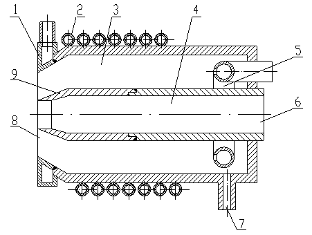
[0069] See figure 1 : A burner for a gasifier. The burner includes a fuel channel 4 coaxial with the gasification agent channel 3 and directly sleeved inside the gasification agent channel 3, the input end of the fuel channel 4 is a fuel input port 6, and the outlet end of the fuel channel 4 is fixedly connected with a burner Nozzle 9, the input end of the gasification agent channel 3 is the gasification agent input port 7, the outlet end of the gasification agent channel 3 is the air injection port 8, and the outside of the gasification agent channel 3 is provided with a cooling water jacket 10 or a cooling water pan Tube 2. In this embodiment, a cooling water coil 2 is arranged outside the gasification agent passage 3, and a jacket 1 on the front face of the burner is arranged on the top of the burner.

[0070] There is a through hole in the center of the jacket 1 on the front face of the burner, which exposes the gas injection port 8 at the front end of the burner gasific...

Embodiment 2

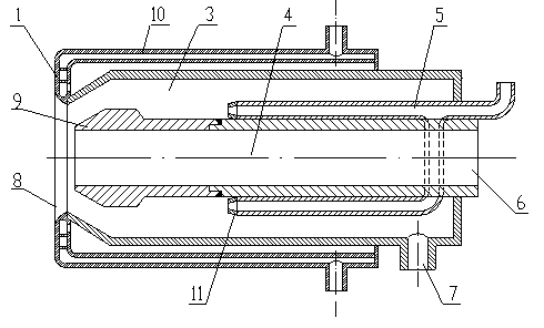
[0077] See figure 2 : a cooling water jacket 10 is arranged outside the gasifying agent channel 3 . The cooling pipe 5 is connected in parallel by at least two straight pipes and installed in the gasification agent passage 3, wherein the coolant input port of the cooling pipe 5 is located outside the gasification agent passage 3, and the coolant output port is configured as a nozzle 11 , and located in the gasification agent channel 3. When the cooling water atomized by the nozzle 11 is sprayed to the burner fuel channel 4 and the burner nozzle 9 at its front end, it is blocked by the tapered inner wall of the gas injection port 8 of the gasification agent channel 3 to form a turbulent water ring. Coated on the 9 parts of the nozzle of the burner, and sprayed onto the jacket 1 part of the front face of the burner, and finally sprayed into the furnace and converted into water vapor by the high temperature in the furnace. All the other are the same as the first embodiment.

Embodiment 3

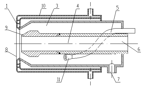
[0079] See image 3 : a cooling water jacket 10 is arranged outside the gasifying agent channel 3 . The cooling pipe 5 is a spiral pipe wound on the outer peripheral wall of the fuel passage 4 . The cooling water input port of the spiral cooling pipe 5 is located outside the gasification agent channel 3, and the coolant output port is structured as a nozzle 11 and is located in the gasification agent channel 3. When the atomized cooling water is sprayed into the burner fuel channel 4 When the burner nozzle 9 at the front end is blocked by the conical inner wall of the gas injection port 8 of the gasification agent channel 3, a turbulent water ring is formed, which covers the burner nozzle and sprays to the jacket of the front face of the burner , and finally sprayed into the furnace and converted into water vapor by the high temperature in the furnace. All the other are the same as the first embodiment.


PUM

PropertyMeasurementUnit
densityaaaaaaaaaa

Abstract

Belonging to the field of gasification equipment, the invention discloses a burner used for a gasifier. The burner comprises: a cooling water jacket or a cooling water coil disposed on a front housing of the burner, a burner front face jacket positioned at the top of the burner, and at least one fuel channel and a gasifying agent channel that is coaxial and directly sleeved with the fuel channel. The burner is characterized in that: at least one cooling pipe is arranged inside the gasifying agent channel, and a coolant inlet of the cooling pipe is located outside the gasifying agent channel, and a coolant outlet of the cooling pipe is positioned inside the gasifying agent channel, the cooling pipe introduces a coolant into the gasifying agent channel from the outside, and the coolant is directly sprayed to the burner head for cooling and finally ejected from an air nozzle. The burner of the invention can effectively prevent high temperature heat radiation and a thermal current from causing high temperature burning loss to the burner head, realize stable burner operation and have effectively extended service life.

Description

technical field [0001] The invention belongs to the field of gasification devices, in particular to the field of gasification furnaces. Background technique [0002] In the entrained bed process, the equipment that injects raw materials into the gasifier for combustion is called a burner. Although this equipment is relatively small compared to the gasifier, the importance of this equipment is no less than that of the gasifier itself. It can be compared with the gasifier in terms of technology, and its characteristics directly affect the stability of the gasifier operation. , so the research on the burner has received extensive attention at home and abroad. [0003] The structural design of the burner is closely related to the life of the burner, and it is one of the most critical technologies in the gasification technology. Therefore, the optimal design of its structure is the key technology to prolong the life of the burner. [0004] On the other hand, the burner is an i...

Claims


Application Information

Patent Timeline
Patent Type & Authority Patents(China)
IPC IPC(8): C10J3/48C10J3/50B05B7/08
Inventor 曹蕾周松锐
Owner DONGFANG BOILER GROUP OF DONGFANG ELECTRIC CORP
Why Eureka
Try Eureka