Tubular inflating filling mold for cast-in-situ concrete
A cast-in-place concrete and tubular technology, which is applied to building components, floor slabs, buildings, etc., can solve the problems of not providing the end structure and manufacturing method, it is difficult to ensure the airtightness of the inflatable carcass, and not providing the manufacturing method of the bladder, etc. , to achieve low transportation costs, improve the mechanical performance of the structure, and save materials
- Summary
- Abstract
- Description
- Claims
- Application Information
AI Technical Summary
Problems solved by technology
Method used
Image
Examples
Embodiment 1
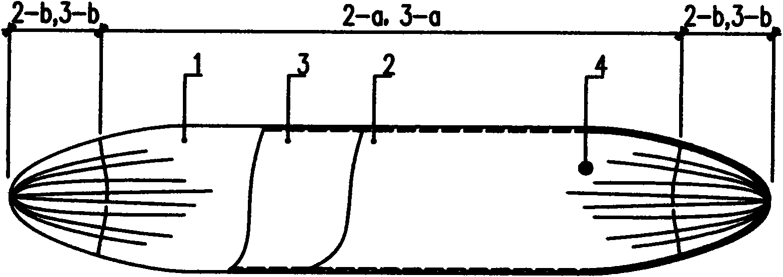
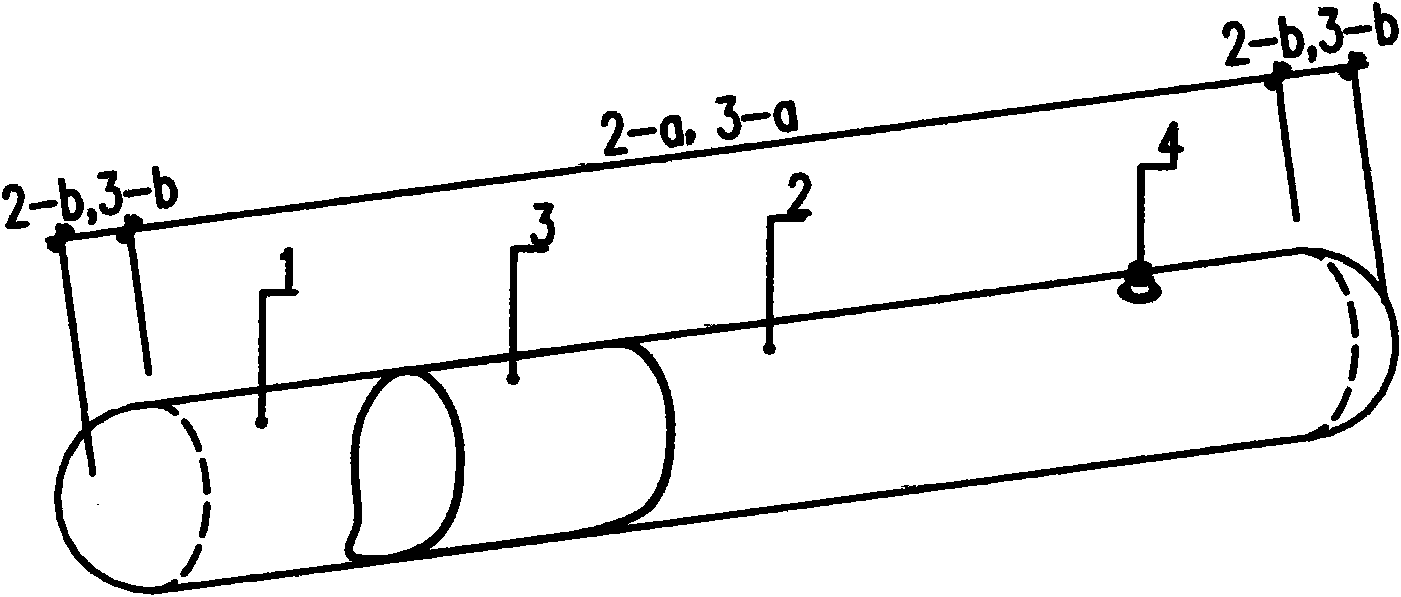
[0034] Embodiment 1: refer to figure 1 , Figure 1-2 , Figure 1-2 , Figure 4-3 The specific implementation method includes an inner bag 3, the inner bag 3 can be made of plastic film, rubber, etc., with openings at both ends as material, and the inner bag 3 is opened on the bag wall at the required position of the inner bag and adopts heat sealing or gluing Method Install the inflation port 4, heat-seal or glue the two ends of the inner bag 3 barrel material at the sealing line 5 to make a gas-barrier inner bag 3, and put the inner bag 3 with the inflation port 4 into the knitting machine , Disposable weaving into the integrity of the outer bag 2 containing the inner bag 3, on the outer bag 2 in an appropriate place to open the inflation port 4 exposed. The material of the outer bag 2 can be high-strength fiber materials such as plastic fibers and glass fibers. Install and fix the manufactured barrel bag at the specified position, and fill in the compressed air or other ...
Embodiment 2
[0035] Embodiment 2: refer to figure 2 , Figure 2-1 to Figure 2-3 The specific embodiment includes an outer bag 2 and an inner bag 3, the outer bag 2 and the inner bag 3 are made of double-layer nested tube materials with openings at both ends, and the inner layer tube material and the outer layer tube material can be bonded or partially glued Together, can also be completely separated. The inner shell material can be made of plastic film, rubber and other materials, and the outer shell material can be made of plastic fiber, glass fiber, non-woven fabric and other materials. After opening the inner and outer layers of the barrel material on the bag wall at the required position, install the inflation port 4 on the bag wall of the inner bag 3 barrel material by heat sealing or gluing, and seal the two ends of the inner bag 3 barrel material at the sealing line 5. Heat-sealing or gluing to make a gas-barrier inner bag 3, folding and binding the tube material of the inner bag...
Embodiment 3
[0036] Embodiment 3: with reference to Fig. 3, Figure 3-1 to Figure 3-3 The specific embodiment includes the inner bag 3, and the inner bag 3 can be made of plastic fiber, glass fiber, non-woven fabric and other materials. The two ends of the barrel material of the inner bag 3 are made into the inner bag 3 by any one or more methods such as fusion, gluing or sewing at the suture line 5, and the inner bag 3 is made of two pieces of plastic film, rubber and other materials. The outer bag 2 is made by means of fusion, gluing, etc., and the outer bag 2 should have an overlapping edge 6 with air-blocking ability around the periphery of the sheet. Appropriate places are opened on the bag wall of the outer bag 2 and the inflation port 4 is installed by heat sealing or gluing. Install and fix the manufactured barrel bag at the specified position, and fill in the compressed air or other gas with the specified pressure before pouring the concrete, that is, the tubular inflatable filli...
PUM
 Abstract
Description
Claims
Application Information
 - R&D
- Intellectual Property
- Life Sciences
- Materials
- Tech Scout
- Unparalleled Data Quality
- Higher Quality Content
- 60% Fewer Hallucinations
Browse by: Latest US Patents, China's latest patents, Technical Efficacy Thesaurus, Application Domain, Technology Topic, Popular Technical Reports.
© 2025 PatSnap. All rights reserved.Legal|Privacy policy|Modern Slavery Act Transparency Statement|Sitemap|About US| Contact US: help@patsnap.com


