
Fiber optic interferometric system for reducing influence of fiber birefringence

A fiber optic interferometry and measurement system technology, applied in measuring devices, measuring heat, measuring ultrasonic/acoustic/infrasonic waves, etc., can solve the problem that the polarization noise of single-mode fiber cannot be effectively suppressed, the polarization rotation cannot be maintained, and the stability of the fiber optic interferometry system is reduced and usability issues

Inactive Publication Date: 2012-04-04
杭州安远科技有限公司
View PDF9 Cites 14 Cited by
  • Summary
  • Abstract
  • Description
  • Claims
  • Application Information

AI Technical Summary

Problems solved by technology

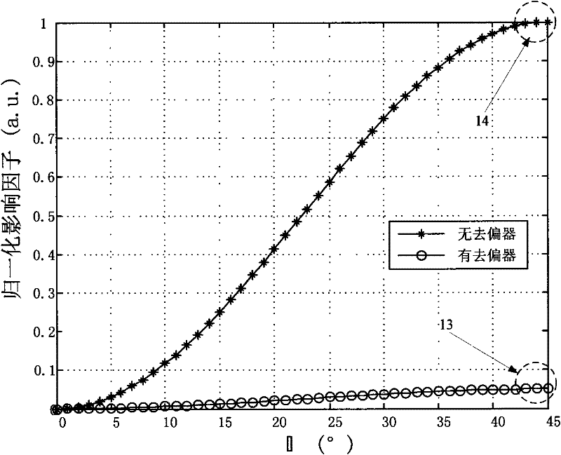
[0025] From the above review of the Michelson fiber optic interferometry device based on the non-ideal Faraday rotating mirror, it can be seen that due to the error in the polarization rotation angle of the Faraday rotating mirror itself, the polarization selection angle will be affected by the central wavelength of the light source, the ambient temperature and the magnetic field. Changes due to changes, making it impossible to maintain a complete 90° polarization rotation, and unable to effectively suppress the polarization noise caused by the birefringence of the single-mode fiber, thus greatly reducing the stability and practicability of the fiber-optic interferometry system

Method used


Image

  • Fiber optic interferometric system for reducing influence of fiber birefringence
  • Fiber optic interferometric system for reducing influence of fiber birefringence
  • Fiber optic interferometric system for reducing influence of fiber birefringence

Examples


Embodiment Construction

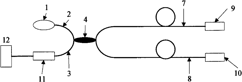
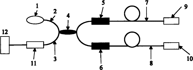
[0035] Figure 2-3 and the following description describe alternative embodiments of the invention to teach those skilled in the art how to make and reproduce the invention. In order to teach the technical solutions of the present invention, some conventional aspects have been simplified or omitted. It should be understood by those skilled in the art that modifications or substitutions from these embodiments will be within the scope of the present invention. Those skilled in the art will appreciate that the features described below can be combined in various ways to form multiple variations of the invention. As such, the invention is not limited to the alternative embodiments described below, but only by the claims and their equivalents.

[0036] Referring to the accompanying drawings, we can see that: figure 2 As shown, the present invention is an optical fiber interferometry system that reduces the influence of optical fiber birefringence. The laser is emitted by the las...


PUM


Abstract

The invention relates to a fiber optic interferometric system for reducing the influence of fiber birefringence. Laser is emitted by a laser device and transmitted to a fiber optic coupler through a source fiber; the laser is split by the coupler and then output to a metric arm and a reference arm of the fiber optic interferometric system respectively, wherein, one path of light is incident to light reflection device of the metric arm through a fiber optic depolarizer of the metric arm and an optical fiber of the metric arm; the reflected light returns to the fiber optic coupler through the original path; the other path of light is incident to a light reflection device of the reference arm through a fiber optic depolarizer of the reference arm and an optical fiber of the reference arm; the reflected light returns to the fiber optic coupler through the original path; the two path of reflected light form an interference light signal in the coupler; the signal is received by a photoelectric detector as an interference signal through an optical fiber of the detector; and the interference signal is transmitted to an operational processing system through a signal transmission line to obtain the size of the outside physical quantity signal. The fiber optic interferometric system used for metering outside physical quantities such as vibration eliminates the influence of the random variation of the polarization state in the ordinary fiber optic interferometric system on the signal of the fiber optic interferometric system.

Description

technical field [0001] The invention relates to an optical fiber interferometric measurement system, in particular to an optical fiber interferometric measurement system with the function of measuring external physical quantities based on a Michelson optical fiber interferometric device. Background technique [0002] The optical fiber interferometry system uses all-fiber devices, which has the characteristics of strong anti-electromagnetic interference, high detection sensitivity, and passive sensor operation. It is widely used in the measurement of physical quantities such as vibration, temperature, and displacement. [0003] According to the light interference theory, only light with the same polarization state can form interference. When there is birefringence in the fiber, the propagation speed of light in different polarization states is different, and the resulting interference signal will also change accordingly. Therefore, when there is birefringence in the fiber, in...

Claims


Application Information

Patent Timeline
IPC IPC(8): G01D21/00G01H9/00G01K11/32G01B9/02G02B27/28
Inventor 王涛
Owner 杭州安远科技有限公司
Learn More