Thermoacoustic-drive thermomagnetic power generating system

A power generation system, thermoacoustic engine technology, applied in the field of thermomagnetic power generation system, to achieve the effect of low maintenance, long life, high power density, high frequency heating and cooling

Active Publication Date: 2012-04-04
TECHNICAL INST OF PHYSICS & CHEMISTRY - CHINESE ACAD OF SCI
View PDF6 Cites 7 Cited by
  • Summary
  • Abstract
  • Description
  • Claims
  • Application Information

AI Technical Summary

Problems solved by technology

[0004] The purpose of the present invention is to solve the problem of mechanical moving parts in the existing thermomagnetic generator and the problem that it is difficult to realize rapid heat exchange, which leads to problems such as difficult production, high maintenance cost, low power density, and difficult expansion, etc., and provides a A thermoacoustic-driven thermomagnetic power generation system; the thermoacoustic-driv

Method used


Image

  • Thermoacoustic-drive thermomagnetic power generating system
  • Thermoacoustic-drive thermomagnetic power generating system
  • Thermoacoustic-drive thermomagnetic power generating system

Examples


Embodiment 1

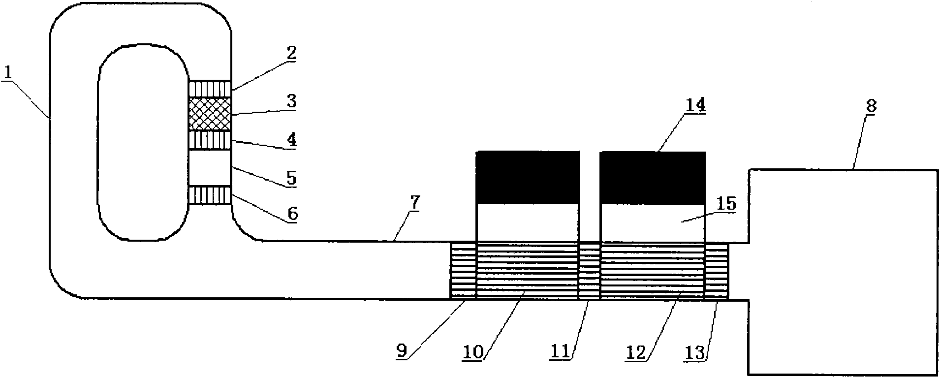
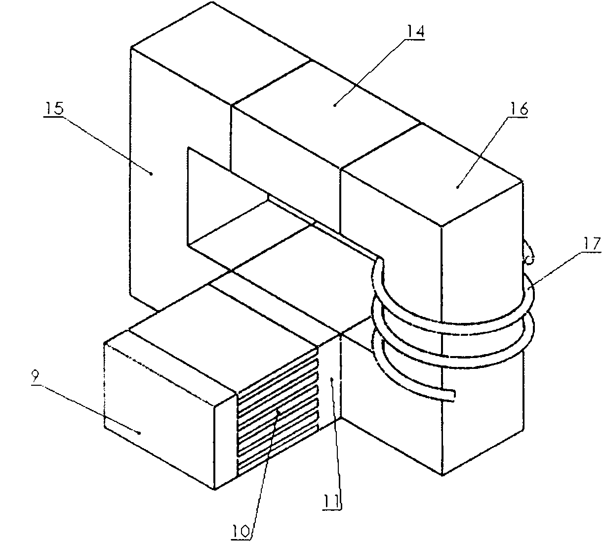
[0037] Picture 1-1 , 1-2 They are the schematic structural diagram of the thermoacoustic-driven thermomagnetic power generation system (Example 1) of the present invention and the three-dimensional schematic diagram of the thermomagnetic generator. It can be seen from the figure that the thermoacoustic-driven thermomagnetic power generation system of the embodiment 1 includes a thermoacoustic engine and A thermomagnetic generator, the thermoacoustic engine is a traveling wave thermoacoustic engine;

[0038] The traveling wave thermoacoustic engine includes a feedback tube 1 connected in sequence to form a traveling wave loop, a heat exchanger 2 at the main room temperature end, a regenerator 3, a heater 4, a thermal buffer tube 5, and a heat exchanger 6 at the secondary room temperature end. Resonant tube 7 and gas storehouse 8; the thermomagnetic generator of the present embodiment is installed at the gas storehouse entrance between described resonant tube 7 and gas storeho...

Embodiment 2

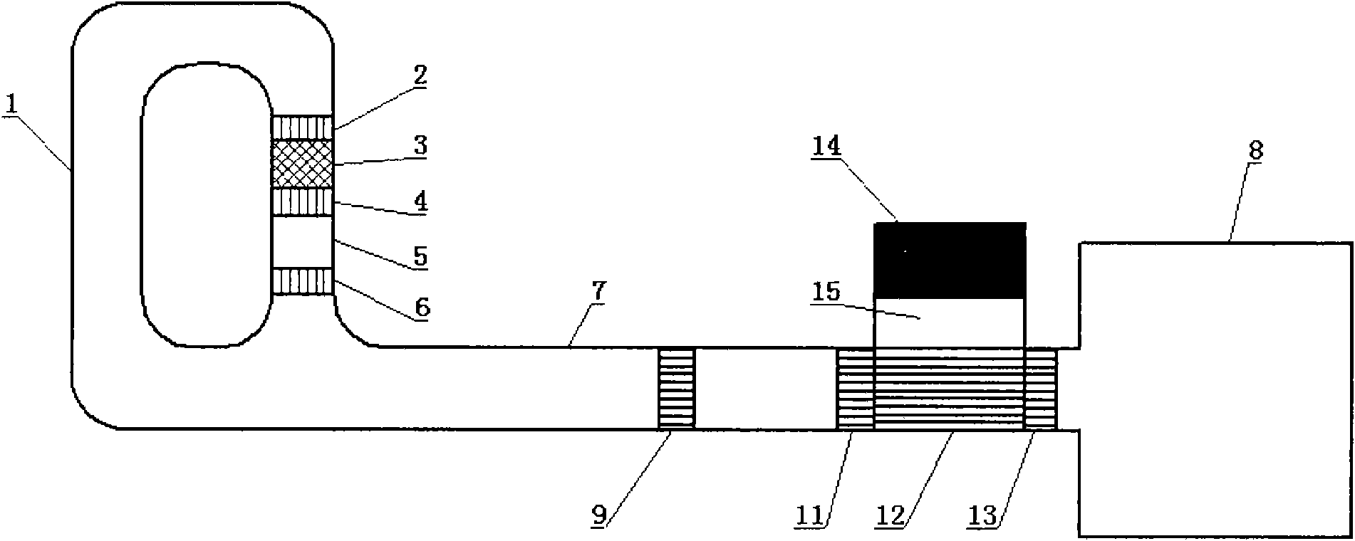
[0048] figure 2 It is a schematic structural diagram of Embodiment 2 of the thermoacoustic-driven thermomagnetic power generation system of the present invention. The thermomagnetic generator can also only place the second magnetically conductive section 12 on one side of the high-temperature heat exchanger 11 as required, and keep the other side hollow; the role of the hollow section is to realize the transition from high temperature to room temperature. Others are the same as embodiment 1.

Embodiment 3

[0050] image 3 It is a schematic structural diagram of Embodiment 3 of the thermoacoustic-driven thermomagnetic power generation system of the present invention. In the present embodiment, a plurality of magnetic conduction sections (three first magnetic conduction sections 10) are placed between the first room temperature heat exchanger 9 and the high temperature heat exchanger 11 of the thermomagnetic generator; 13 and the high-temperature heat exchanger 11 place a plurality of magnetically conductive sections (three second magnetically conductive sections 12); each magnetically conductive section forms a magnetic circuit with its own permanent magnet and magnetically conductive material; The temperature in it decreases stepwise from high to low; each thermomagnetic power generation unit works independently, and the upper coils of each thermomagnetic power generation unit can independently drive electric loads, and can also be connected in sequence to drive electric loads, ...


PUM


Abstract

A thermoacoustic-drive thermomagnetic power generating system comprises a thermoacoustic engine and a thermomagnetic power generator mounted on a resonance tube of the thermoacoustic engine. The thermomagnetic power generator comprises two room-temperature heat exchangers, a high-temperature heat exchanger, at least one magnet conductive section, a pair of magnetizing blocks and a permanent magnet, wherein the high-temperature heat exchanger is arranged between the two room-temperature heat exchangers, the magnet conductive sections are mounted among the room-temperature heat exchangers and the high-temperature heat exchanger, the magnetizing blocks are disposed oppositely, the permanent magnet is clamped between one ends of the magnetizing blocks, the magnet conductive sections are clamped between the other ends of the magnetizing blocks, a coil is sleeved on the magnetizing blocks, and each magnet conductive section, the permanent magnet and the pair of magnetizing blocks form a magnetic loop. When alternating flowing fluid in a system moves back and forth among the room-temperature heat exchangers and the high-temperature heat exchanger, sheets of magnetized materials of the magnet conductive sections are heated or cooled; magnetic resistance and magnetic flux of the magnetic loop vary along with variation of magnetic conductivity of the magnetized materials, and the coil generates induced electromotive force and generates electric energy then. The thermoacoustic-drive thermomagnetic power generating system is totally free of mechanical moving parts, high in reliabilityand power density and the like.

Description

technical field [0001] The invention relates to a thermomagnetic power generation device, in particular to a thermoacoustic driven thermomagnetic power generation system. Background technique [0002] Thermoacoustic engines have the advantages of good energy adaptability, no moving parts, and high reliability. It is a device that uses thermal energy to generate fluid reciprocating motion; in addition, its operating frequency is very wide, generally in the range of several hertz to thousands of hertz. A thermomagnetic generator is a device that uses high-permeability materials to undergo a huge change in the permeability near the Curie temperature, which causes a change in the magnetic flux passing through the coil in the magnetic circuit, thereby generating electrical energy. However, the thermomagnetic power generation system needs to alternately heat and cool the magnetic material, and how to realize rapid heating and cooling of the magnetic material is one of the difficu...

Claims


Application Information

Patent Timeline
IPC IPC(8): H01L37/04
Inventor 罗二仓吴张华
Owner TECHNICAL INST OF PHYSICS & CHEMISTRY - CHINESE ACAD OF SCI
Why Eureka
Try Eureka