Hall switch
A technology of Hall switch and magnetic conductive sheet, applied in the field of switches, can solve the problems of magnetic block leakage, low sensitivity, poor waveform, etc., and achieve the effect of reducing the magnetic leakage phenomenon and increasing the sensitivity
- Summary
- Abstract
- Description
- Claims
- Application Information
AI Technical Summary
Problems solved by technology
Method used
Image

Examples
Embodiment ( 1
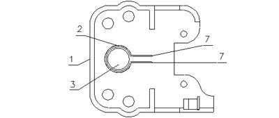
[0021] figure 1 is a structural schematic diagram of the Hall switch of the present invention, please refer to figure 1 , a Hall switch, comprising: a casing 1, the casing 1 is made of a non-magnetic material, wherein a magnetic block 3 is rotatably installed in the casing 1; a magnetic sheet 2 is wound around On the outside of the magnetic block 3, the magnetic flux leakage of the magnetic block 3 in the magnetic conductive sheet 2 is reduced by adopting a winding method, the magnetic flux of the magnetic conductive sheet 2 becomes larger, and the sensitivity of the Hall switch is higher when the magnetic block 3 is rotated. The response is faster, and the output waveform is also smoother; the magnetic sheet 2 has two lead-out ends 7, and the two lead-out ends 7 do not touch each other. The large size causes the measuring device to be unable to accurately determine the direction of rotation of the magnetic block and thus fail to perform switch operations, and the measuring d...
Embodiment ( 2
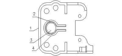
[0026] figure 2 It is a schematic structural diagram of Embodiment 2 of the Hall switch of the present invention, please refer to figure 2 , on the basis of Embodiment 1, the outer surface of the magnetically conductive sheet 2 of the Hall switch of the present invention is provided with a magnetic isolating plate 4, the magnetically isolating plate 4 completely covers the outer surface of the magnetically conducting sheet 2, and the magnetically isolating plate 4 is used In order to isolate the interference of the external magnetic field, it avoids the decrease of precision or even failure when the Hall switch of the present invention is used in an occasion with strong electromagnetic radiation.
[0027] Further, a magnetic isolation cover can be placed above the magnetic isolation plate 3, which can isolate the interference from the top of the magnetic conductive sheet 2 that cannot be isolated by the magnetic isolation plate 3, so as to achieve a better anti-interference ...
Embodiment ( 3
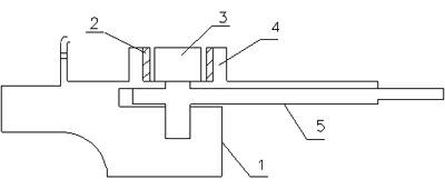
[0029] image 3 is a structural cross-sectional view of Embodiment 3 of the Hall switch of the present invention, Figure 4 is a schematic structural diagram of Embodiment 3 of the Hall switch of the present invention, please refer to image 3 , Figure 4 , on the basis of the above-mentioned embodiments, the Hall switch of the present invention also includes a rocker 5 connected to the magnetic block 3, the rocker 5 is installed between the magnetic block 3 and the housing 1, and the magnetic block is driven by the rocker 5 3. It is more convenient to rotate; the rocker 5 is made of non-magnetic material to avoid magnetic flux leakage and to avoid the introduction of external interference.
PUM
 Abstract
Description
Claims
Application Information
 - R&D
- Intellectual Property
- Life Sciences
- Materials
- Tech Scout
- Unparalleled Data Quality
- Higher Quality Content
- 60% Fewer Hallucinations
Browse by: Latest US Patents, China's latest patents, Technical Efficacy Thesaurus, Application Domain, Technology Topic, Popular Technical Reports.
© 2025 PatSnap. All rights reserved.Legal|Privacy policy|Modern Slavery Act Transparency Statement|Sitemap|About US| Contact US: help@patsnap.com