Supercharge Your Innovation With Domain-Expert AI Agents!

Tangential-inlet-type gas supersonic velocity cyclone separating device

A swirl separation device and swirl separation technology, applied in separation methods, dispersed particle separation, mining fluids, etc., can solve problems such as unfavorable droplet growth, weak swirl ability, and destruction of low-temperature and low-pressure environments, and achieve the suppression of boundary layers Separation phenomenon, improvement of pressure recovery ability, and effect for stable operation

Inactive Publication Date: 2012-04-11
文闯
View PDF21 Cites 6 Cited by
  • Summary
  • Abstract
  • Description
  • Claims
  • Application Information

AI Technical Summary

Problems solved by technology

[0003] The main structure of the supersonic cyclone separator includes components such as Laval nozzle, cyclone device and diffuser pipe. According to the installation position of the cyclone device, there are two typical structures of the supersonic cyclone separator: one The swirl device is installed in the supersonic section behind the nozzle to generate the swirl, so the swirl device is also called the supersonic wing. In this kind of structure, since the speed conversion occurs under the supersonic condition, the supersonic wing is easy to generate shock. Waves destroy the low temperature and low pressure environment, which is not conducive to the growth of droplets and reduces the separation efficiency of the supersonic separator. Representative patents mainly include foreign US 6513345 B1, US 6524368B2, US 3773825 B2, US 6962199 B1, US 7261766 B2, US 7318849 B2, US 7494535 B2, WO2003 / 092850 A1, WO 2004 / 020074 A1 and domestic ZL 200410074338.8, etc.; the other is to install the swirl device at the inlet of the nozzle so that the gas enters the nozzle in the form of swirl The expansion and cooling, the main patents are foreign US7357825 B2, US 2008 / 0196581 A1, US 2010 / 0147021 A1, EP 1131588 B1, US 6372019 B1, US 2010 / 0147023 A1 200910023458.8 and 6, ZL 200910023458.8 and Application. .

Method used


Image

  • Tangential-inlet-type gas supersonic velocity cyclone separating device
  • Tangential-inlet-type gas supersonic velocity cyclone separating device
  • Tangential-inlet-type gas supersonic velocity cyclone separating device

Examples


Embodiment Construction

[0012] The structural features and working principles of the present invention will be further described below in conjunction with the accompanying drawings.

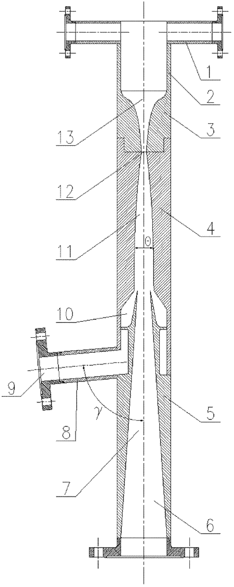
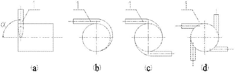
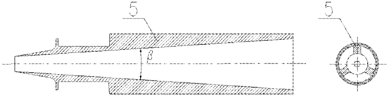
[0013] see figure 1 , the present invention is mainly composed of a tangential inlet section 1, a steady flow section 2, a constriction section 3, an expansion section 4, a diffuser pipe 5, a liquid discharge pipe 8, a dry gas outlet 6 and a liquid outlet 9; the area of ​​the constriction section 3 gradually The smaller subsonic contraction and swirl strengthen the flow channel 13, and the expansion section 4 forms a supersonic swirl separation flow channel 11 whose area gradually increases. The expansion angle of the supersonic swirl separation flow channel 11 is 0.5°≤θ≤1.5°. The junction of the sonic contraction and swirl flow enhancement channel 13 and the supersonic swirl separation flow channel 11 constitutes the throat 12 with the smallest area; , The drain pipe 8 and the liquid outlet 9 communicate with each oth...


PUM


Abstract

The invention relates to a tangential-inlet-type gas supersonic velocity cyclone separating device which mainly comprises a tangential inlet section, a contracting section, an expanding section and a diffuser pipe and is applied to the fields of multi-component gas mixture separation, and the like. The tangential inlet section is used for guiding the gas to enter into a runner along a tangential direction, thereby forming a stable cyclone; after entering into the contracting section, the airflow is stably accelerated and achieves a sound velocity on a laryngeal part; the runner area and the rotating radius are reduced, so that the cyclone is enhanced according to the angular momentum conservation law; in the expanding section, the airflow is expanded and reaches a supersonic velocity, thereby forming a low temperature and a low pressure and condensing the water in the gas or the water and heavy hydrocarbon component in natural gas; and meanwhile, condensed liquid drops are thrown toward a wall surface under the effect of a huge centrifugal force generated by the rotation of airflow, thereby efficiently realizing gas-liquid separation; and the liquid enters into a liquid accommodating chamber and the dry gas is located at the center of a pipeline and flows out after being pressed back by the diffuser pipe. The tangential-inlet-type gas supersonic velocity cyclone separating device is simple in structure, is high in processing and assembling precision, requires no added chemical agent, supports an unmanned operation and is wide in application prospect.

Description

Technical field: [0001] The invention relates to a tangential inlet type gas supersonic cyclone separation device, which belongs to the technical field of low-temperature condensation and cyclone separation of multi-component mixed gas. Background technique: [0002] Supersonic cyclone separation technology is a new technology applied in the fields of natural gas gathering, transportation, processing and treatment. The recompression and other processing processes are completed in a closed and compact device, which has the advantages of simplicity, reliability, no leakage, no need for chemicals, and unattended support. Compared with the traditional heating antifreeze and antifreeze antifreeze natural gas gathering and transportation processes The investment and operating costs of the natural gas gathering and transportation system will be reduced by 10-25%. Foreign companies Twister BV and ENGO Petroleum Company have carried out relevant research work on supersonic cyclone s...

Claims


Application Information

Patent Timeline
IPC IPC(8): B01D53/24B01D45/16B01D5/00E21B43/34
Inventor 文闯曹学文杨燕
Owner 文闯
Features
  • R&D
  • Intellectual Property
  • Life Sciences
  • Materials
  • Tech Scout
  • Unparalleled Data Quality
  • Higher Quality Content
  • 60% Fewer Hallucinations
Learn More