
Powder decarburization system

A decarburization and powder technology, which is applied in the field of decarburization systems, can solve the problems of difficult and precise control of decarburization temperature and uncontrollable vanadium extraction temperature, and achieve the effect of precise temperature control.

Inactive Publication Date: 2013-01-16
单文奎
View PDF4 Cites 0 Cited by
  • Summary
  • Abstract
  • Description
  • Claims
  • Application Information

AI Technical Summary

Problems solved by technology

At present, in the vanadium pentoxide industry, vanadium and carbon are mostly symbiotic ores, and the vanadium extraction temperature cannot be controlled due to the presence of carbon in the vanadium extraction process
[0003] In the prior art, there are mainly two types of decarbonization devices, one is tunnel block decarburization, and the other is fluidized bed particle decarbonization. However, when vanadium is extracted from carbon-containing vanadium ore soil, due to The combustion temperature is about 650°C, and the temperature for extracting vanadium is 850°C-900°C. When extracting vanadium from carbon-containing vanadium ore, decarburization treatment must be carried out first, but it is often difficult to accurately determine the decarburization temperature during decarburization. control, so the extraction of vanadium from carbonaceous vanadium ore soils has not been successful

Method used


Image

  • Powder decarburization system

Examples


Embodiment Construction

[0025] The present invention will be described in further detail below in conjunction with the accompanying drawings and specific embodiments.

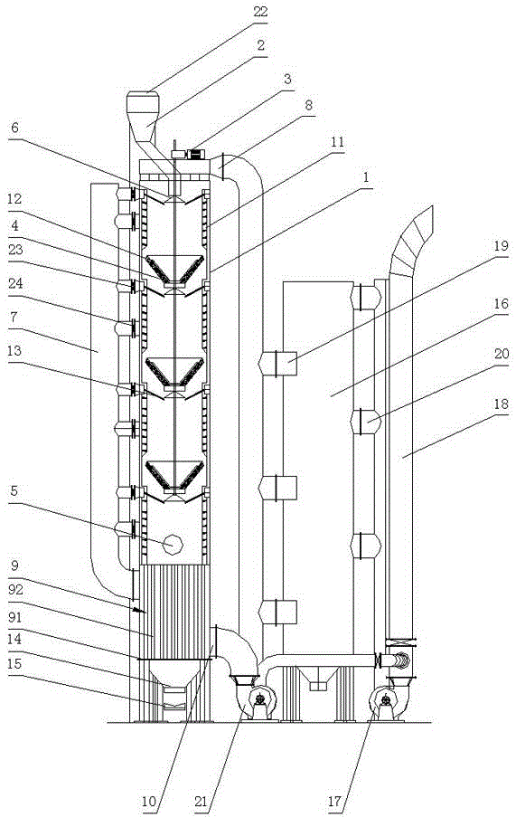
[0026] figure 1 It is a schematic diagram of the structure of the powder decarburization system, as shown in the figure. The powder decarburization system includes decarburization furnace 1, feed hopper 2, rotary and lifting actuator 3, collecting hopper 4, burner 5, distributor 6, air inlet main pipe 7, ore hoist 22, ash hopper 14, conveyer Material device 15, high temperature dust collector 16, high temperature fan 17, smoke exhaust pipe 18 and circulation fan 21.

[0027] Wherein, the feed hopper 2 is arranged on the top of the decarburization furnace 1 , and the outlet of the feed hopper 2 extends into the decarburization furnace 1 . The discharge port of the mineral hoist 22 is located directly above the feed hopper 2 .

[0028] The top of the decarburization furnace 1 is provided with a flue gas outlet 8, and the bottom is pr...


PUM


Abstract

The invention discloses a powder decarburization system. The powder decarburization system comprises a decarburization furnace, a feed hopper, a rotating and lifting actuator, material-collecting hoppers, a combustor, material distributors, a high temperature dust remover and a main blast pipe, wherein the feed hopper is arranged on the top of the decarburization furnace; the top of the decarburization furnace is provided with a flue gas outlet, the bottom is provided with a gas-solid heat exchanger; the inside of the decarburization furnace is provided with the material-collecting hoppers, air-distributing pipes are evenly arranged on the inner wall; the combustor is arranged between the lowest material-collecting hopper and the gas-solid heat exchanger; the air outlet of the gas-solid heat exchanger is communicated with the main blast pipe, the air-distributing pipes are communicated with the main blast pipe; the material distributors are arranged below the outlets of the feed hopper and the material-collecting hoppers; and the material distributors are driven by the rotating and lifting actuator. The powder decarburization system adopts powder decarburization, mineral aggregatemoves down through the material-collecting hoppers, the heat generated through decarburization is utilized to preheat the mineral aggregate, the gas-solid heat exchanger is used to preheat air, the waste heat of the high temperature mineral aggregate is used to preheat air, the combusted flue gas is circulated to the inside of the furnace through the back part of the high temperature dust removerso as to adjust the temperature; and instant decarburization is realized in the decarburization furnace and the decarburization temperature is accurately controlled.

Description

technical field [0001] The invention relates to a decarbonization system, in particular to a powder decarbonization system used in the production process of extracting vanadium pentoxide from carbon-containing vanadium ore soil. Background technique [0002] As a material with special properties, vanadium is added to metal building materials in the form of alloys, which can significantly improve the strength and oxidation resistance of metal materials. At present, in the vanadium pentoxide industry, vanadium and carbon are mostly symbiotic ores, and the vanadium extraction temperature cannot be controlled due to the presence of carbon in the vanadium extraction process. [0003] In the prior art, there are mainly two types of decarbonization devices, one is tunnel block decarburization, and the other is fluidized bed particle decarbonization. However, when vanadium is extracted from carbon-containing vanadium ore soil, due to The combustion temperature is about 650°C, and t...

Claims


Application Information

Patent Timeline
Patent Type & Authority Patents(China)
IPC IPC(8): C22B1/02C22B34/22C01B19/02
CPCY02P20/129
Inventor 单文奎
Owner 单文奎
Learn More