
Rigid grid structure for constraining sludge flow and using method thereof

A grid structure and rigid technology, applied in infrastructure engineering, soil protection, construction, etc., can solve problems such as weak substratum can not meet the requirements, pipelines affect the use of buildings, and the bearing capacity of the foundation is not improved. The effect of simple structure, improving project safety and reducing project cost

Active Publication Date: 2014-04-30
中煤江南建设发展集团有限公司
View PDF6 Cites 0 Cited by
  • Summary
  • Abstract
  • Description
  • Claims
  • Application Information

AI Technical Summary

Problems solved by technology

[0008] (1) The cost of silt reinforcement is high, but the bearing capacity of the foundation is not greatly improved;
[0009] (2) The sludge reinforcement takes a long time. If the surcharge preloading process is adopted, the treatment time is 1 to 3 years to achieve the effect of discharging the pore water in the sludge;
[0010] (3) The reinforcement depth is effective. For example, the reinforcement depth of vacuum preloading is about 10 meters, and the reinforcement depth of ordinary mixing piles is about 15 meters. This will cause the weak underlying layer to fail to meet the requirements in some cases;
[0011] (4) The post-construction settlement is large, usually manifested as excessive surface settlement, and cracked pipelines seriously affect the use of buildings and structures after they are completed
[0012] (5) Due to the large ground subsidence, the foundation of the building is exposed, which is very unfavorable to the stress of the foundation of the completed building
[0013] (6) For road and railway subgrades, large post-construction settlement will seriously affect driving safety

Method used


Image

  • Rigid grid structure for constraining sludge flow and using method thereof
  • Rigid grid structure for constraining sludge flow and using method thereof
  • Rigid grid structure for constraining sludge flow and using method thereof

Examples


Embodiment 1

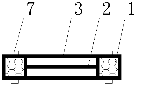
[0044] refer to figure 1 and figure 2 As shown, a rigid grid structure for restricting silt flow of the present invention includes at least two vertical supports 1, the number of vertical supports 1 is determined according to the specific conditions of the construction site, and the vertical supports 1 It can form a planar bent structure, a space tetrahedron, a hexahedron, a prism, etc. The cross-sectional shape of the vertical support 1 can be square, triangular, circular or other multi-shaped shapes, depending on the specific circumstances. The number of the vertical supports 1 in the example is two, and the material of the vertical supports 1 can adopt common construction materials such as metal, concrete; The connector 2 is a collar, and the collar and the vertical support 1 are fixedly connected by bolts 7; after the vertical support 1 and the connector 2 are connected and fixed, a rigid grid structure is formed; the rigid grid structure is wrapped with The first flexi...

Embodiment 2

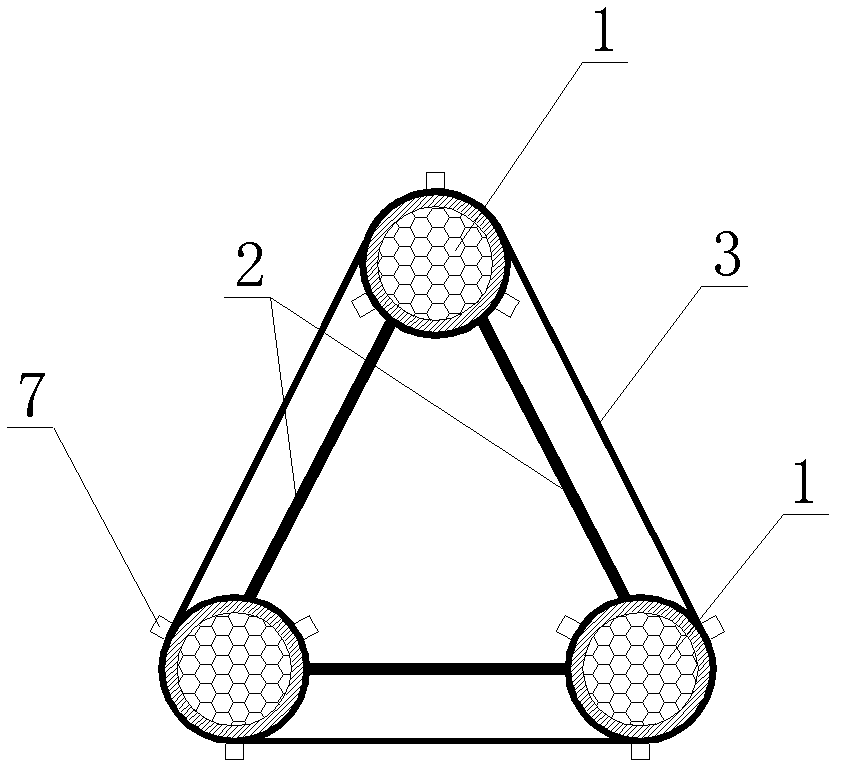
[0049] refer to image 3 As shown, a rigid grid structure for restricting silt flow of the present invention is basically the same in structure as in Embodiment 1, the difference is that the number of vertical supports 1 is three, arranged in an equilateral triangle, and The connecting parts 2 cooperate to form a space-rigid grid structure, and a first flexible grid 3 is arranged on the periphery of the space-rigid grid structure formed by the three vertical supports 1 . Its method of use is on the basis of the method of embodiment 1, in the formed connected closed space constraint zone, continue to repeat the pressing operation of the rigid grid structure, so that the silt that can be restrained by the adjacent rigid grid structure The ranges partially overlap each other to form an overall spatially constrained block.

Embodiment 3

[0051] refer to Figure 4 As shown, a rigid grid structure for restricting sludge flow of the present invention is basically the same in structure as in Embodiment 2, the difference is that the number of vertical supports 1 is four, arranged in a square and combined with rigid The grids form a spatially rigid grid structure, and first flexible grids 3 are provided on both the periphery and the inner periphery of the rigid grid structure. Its method of use is the same as in Example 2.


PUM


Abstract

The invention discloses a grid structure for reinforcing sludge and a using method thereof and belongs to the technical field of sludge treatment. The technical key point is that: the structure comprises at least two vertical supporting pieces, wherein a plurality of connecting pieces are arranged among the vertical supporting pieces; and the vertical supporting pieces and the connecting pieces form a rigid grid structure. The method comprises the following steps of: (1) prefabricating the rigid grid structure; (2) calculating distribution density and range of the rigid grid structure according to depth, position and range of the sludge of which flow is needed to be constrained; and (3) pressing the prefabricated rigid grid structure in the sludge of which the flow is to be constrained. The invention aims to provide a grid structure with a simple structure for rapid sludge treatment, and after treatment, the sludge bearing capacity is improved, and sludge compression settlement is reduced; moreover, the structure is used for reinforcing the sludge.

Description

technical field [0001] The present invention relates to a structure for sludge handling, and more particularly, to a rigid grid structure for restricting the flow of sludge. The invention also relates to a method of using the spatial grid structure. Background technique [0002] There are generally 30 to 40 meters of silt or muddy soil in the strata of coastal areas. Soft soil is generally saturated, flow-plastic, micro-bedding development, containing shell fragments, see humus, mainly composed of silt, muddy silty clay, or muddy clay. The engineering properties of soft soil have the following characteristics: (1) high natural water content (2) large natural void ratio (3) high compressibility (4) weak permeability (5) small consolidation coefficient (6) small cohesion ( 7) Low bearing capacity (8) Strong thixotropy, etc. In the treatment of soft soil, the main measures are as follows: [0003] (1) It is said that mixing piles, rotary grouting piles, gravel piles, CFG pi...

Claims


Application Information

Patent Timeline
Patent Type & Authority Patents(China)
IPC IPC(8): E02D3/00
Inventor 马文旭夏晓丹
Owner 中煤江南建设发展集团有限公司
Learn More