
Adjustable guide vane system of gas turbine power turbine

A technology for power turbines and gas turbines, which is used in the lubrication of turbine/propulsion devices, engine components, and engine lubrication. The effect of reducing fuel consumption

Active Publication Date: 2012-04-11
HARBIN GUANGHAN POWER TECH DEV CO LTD
View PDF5 Cites 16 Cited by
  • Summary
  • Abstract
  • Description
  • Claims
  • Application Information

AI Technical Summary

Problems solved by technology

[0005] The present invention aims to solve the problem that the existing gas turbine power turbine turnable guide vane system has a complex sealing structure and low working reliability, and further provides a gas turbine power turbine turnable guide vane system

Method used


Image

  • Adjustable guide vane system of gas turbine power turbine
  • Adjustable guide vane system of gas turbine power turbine
  • Adjustable guide vane system of gas turbine power turbine

Examples


specific Embodiment approach 1

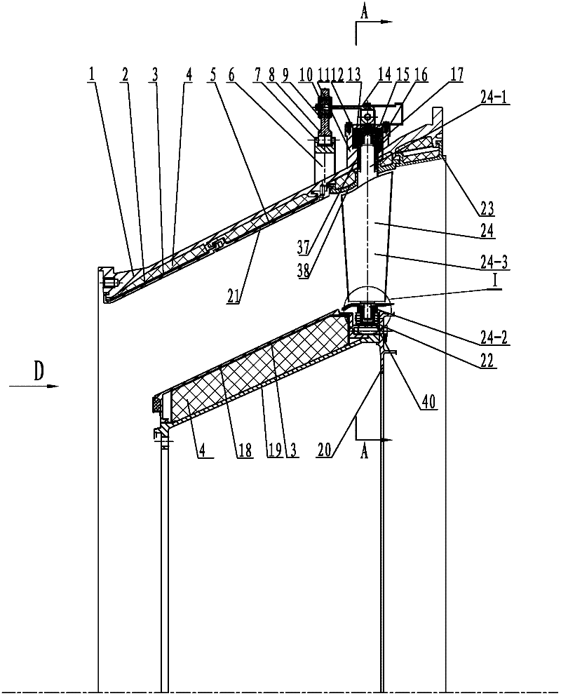
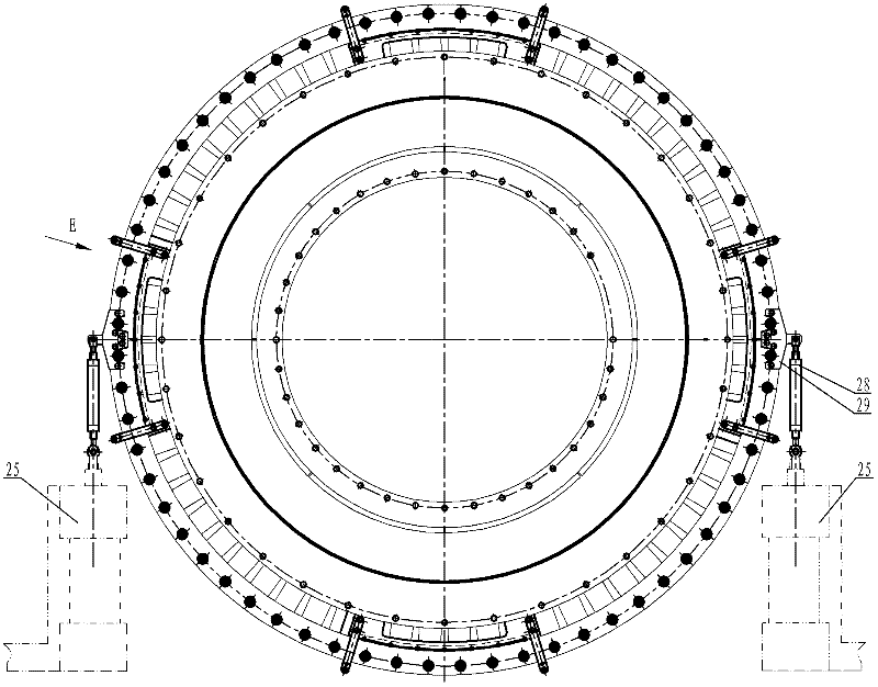
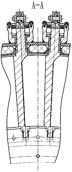
[0009] Specific implementation one: as Figure 1~6 As shown, the gas turbine power turbine steerable vane system of this embodiment includes a casing 1, a front outer casing 2, a first steel belt 3, a second steel belt 21, a rear outer casing 5, a guide rail 6, a roller 7, a linkage Ring 8, retaining spring 9, first bearing sleeve 10, second bearing sleeve 11, ceramic shaft 12, rocker arm 14, end cover 15, inner casing 18, adapter tube 19, flange 20, retaining ring 23, optional Guide vane 24, ball bearing 33, dial 35, pointer 36, ceramic bushing 37, guard plate 38, left half cylinder 39, flexible graphite bushing 40, right half cylinder 42, two forks 29, two elastics 28, two actuators 25 and a plurality of silicate fiber needled felt layers 4, the first steel belt 3 is installed on the upper end surface of the front housing cover 2, and the second steel belt 21 is installed on the rear housing On the upper end surface of the cover 5 , the front outer cover 2 , the rear outer ...

specific Embodiment approach 2

[0010] Specific implementation two: as figure 1 and Figure 5 As shown, the turbine rotatable guide vane system in this embodiment further includes a graphite gasket 13 , and the graphite gasket 13 is located between the end cover 15 and the ceramic shaft 12 . In this way, the flexible graphite gasket 13 reduces the loss of gas leakage caused by the rotatable guide vanes, and ensures that the operating performance of the gas turbine part under non-design conditions is greatly improved and the operation is safer. Other components and connection methods are the same as in the first embodiment.

specific Embodiment approach 3

[0011] Specific implementation three: as figure 1 As shown, the turbine rotatable guide vane system in this embodiment further includes a first gasket 16 , and the first gasket 16 is located between the end cover 15 and the second bearing sleeve 11 . Other compositions and connection methods are the same as those in the first or second embodiment.


PUM


Abstract

The invention discloses an adjustable vane system of a gas turbine power turbine, which relates to an adjustable guide vane of a turbine. The invention aims at solving the problem that the traditional adjustable guide vane system of the gas turbine power turbine has a complicated sealing structure and low functional reliability. The other end of a rocking arm is connected with the upper end of a ceramic rotating shaft, a second bearing sleeve is arranged on the upper end surface of a casing, an adjustable guide vane comprises an upper guide vane shaft, a lower guide vane shaft and an adjustable guide vane main body, the upper guide vane shaft, the adjustable guide vane main body and the lower guide vane shaft are fixedly assembled into a whole in sequence from top to bottom, the upper guide vane shaft and the lower guide vane shaft are coaxial, a ceramic shaft sleeve is sleeved on the upper guide vane shaft, the upper end of the upper guide vane shaft passes through the casing to be fixedly connected with the ceramic rotating shaft, an end cover is fixedly arranged on the upper end surface of the second bearing sleeve, an expanded graphite shaft sleeve is sleeved on the lower guide vane shaft, a left half cylinder and a right half cylinder are fixedly assembled into a whole. The adjustable guide vane system of the gas turbine power turbine provided by the invention is designedfor regulating turbine stage through-current capability.

Description

technical field [0001] The invention relates to a turbine steerable vane system, in particular to a gas turbine power turbine steerable vane system. Background technique [0002] A remarkable feature of a gas turbine is that its output power and thermal efficiency decrease rapidly with the reduction of operating conditions. Therefore, the use of the power turbine steerable guide vane system can improve the power and thermal efficiency of the unit under some non-design working conditions. So far, the steerable guide vane systems of gas turbine power turbines used in engineering abroad mainly include: the WR21 gas turbine in the United States. By using intercooling, heat recovery and adjustable guide vane technology, this type of gas turbine is simpler than the same power level. Cycling gas turbines save up to 30% of fuel annually. The power turbine steerable vanes can play an important role in the commissioning process of the unit, which can effectively solve the problem of...

Claims


Application Information

Patent Timeline
IPC IPC(8): F02C7/06
Inventor 刘宇闫锦生卫嘉郁顺旺王林梁晨牛夕莹何建元张时瑞
Owner HARBIN GUANGHAN POWER TECH DEV CO LTD
Learn More