Cutting machine

A cutting machine and cutting knife technology, which is applied to metal sawing equipment, sawing machine equipment, metal processing equipment, etc., to achieve the effect of reducing or noise, eliminating noise, and eliminating adverse effects

Inactive Publication Date: 2012-04-11
MAKITA CORP
View PDF3 Cites 7 Cited by
  • Summary
  • Abstract
  • Description
  • Claims
  • Application Information

AI Technical Summary

Problems solved by technology

[0005] But people can think of the following situation: the above-mentioned high-frequency current generated near the motor is conducted through the cutting machine body and the metal components on the sid

Method used


Image

  • Cutting machine
  • Cutting machine
  • Cutting machine

Examples


Example Embodiment

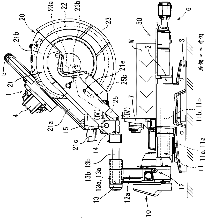
[0021] The following is based on Figure 1 to Figure 4 Embodiments of the present invention will be described. figure 1 It is an overall side view showing the cutting machine 1 in the embodiment of the present invention. In the illustrated embodiment, as an example of the cutting machine 1 , a sliding circular saw as a desktop cutting machine is exemplified. It allows the cutting machine body 20 to slide back and forth. exist figure 1 , the user is located on the right side of the cutting machine 1. In the following description, the user side ( figure 1 The middle right side) is the front side, the side away from the user ( figure 1 Middle left) is the rear side. In addition, the left and right directions are based on the user. In a normal cutting operation, the user moves the cutter body 20 from the near side to the rear side to perform cutting. Therefore, the direction towards the rear side is also referred to as the cutting travel direction.

[0022] The cutting ma...


PUM


Abstract

A table top circular saw cutting machine provided, for example, with a table on which a material to be cut is placed and with a cutting machine body having a saw blade rotated by an electric motor may have a phenomenon in which a high-frequency electric current generated in the vicinity of the electric motor is amplified on the table side to become noise to peripheral equipment. The invention reduces the noise. A cutting machine is configured in such a manner that conduction of a high-frequency electric current is blocked by installing insulating members (16, 16) on a support shaft (15) for supporting the cutting machine body (20) so that the cutting machine body can be tilted in the vertical direction relative to a body support section (50) which is mainly composed of a table.

Description

technical field [0001] The present invention relates to a cutting machine, which is, for example, a stationary circular saw such as a desktop circular saw or a table saw, or a portable circular saw. Background technique [0002] For example, a technology about circular saws is disclosed in the following patent documents. For example, a desktop circular saw has: a workbench, which is used to place the material to be cut; a cutting machine body, which is supported above the workbench and can bob up and down. The cutting machine body has a circular cutting knife that is driven by a motor as a power source. The user can swing the body of the cutting machine downward to make the rotating cutting knife cut into the material to be cut for cutting. [0003] In the above-mentioned cutting machine, the workbench and related components are usually made of metal materials such as steel or non-ferrous metal materials such as aluminum alloy. Wherein, the cutting machine body with the m...

Claims


Application Information

Patent Timeline
IPC IPC(8): B23D47/00
CPCB23D47/005B23D45/048Y10T83/7793Y10T83/7755
Inventor 可儿利之木村佳弘柴田美德
Owner MAKITA CORP
Why Eureka
Try Eureka