Heat treatment apparatus

A technology for heat treatment devices and treatment containers, which is applied in the manufacture of electrical components, semiconductor/solid-state devices, circuits, etc. It can solve the problems of low conductance of cooling water flow path, hindering the flow of cooling medium, and inability to cool efficiently, so as to increase the configuration density. , improve energy efficiency, reduce the effect of energy

Inactive Publication Date: 2012-04-11
TOKYO ELECTRON LTD
View PDF10 Cites 13 Cited by
  • Summary
  • Abstract
  • Description
  • Claims
  • Application Information

AI Technical Summary

Problems solved by technology

[0004] In the technique described in the aforementioned Japanese Patent Laid-Open No. 2002-64069, since the arrangement density of the lamps and the luminous density of each lamp are limited, the heating efficiency is insufficient.
[0005] In addition, in the technique described in the above-mentioned U.S. Patent No. 5,840,125, since the lamps are arranged vertically, the arrangement density of the lamps can be increased. wafer, so a high percentage of heat is absorbed on the light pipe side, and the energy efficiency is not good
In addition, the temperature of the light guide as a reflector increases significantly due to the light received from the lamp, so it is necessary to cool the light guide by flowing a cooling medium such as cooling water between the light guides. Since the light guide is installed for each lamp, the light guide The flow of the cooling medium is blocked, and the conductance of the cooling water flow path becomes low, and efficient cooling cannot be performed. In order to ensure sufficient cooling, the supply pressure of the cooling water needs to be increased

Method used


Image

  • Heat treatment apparatus
  • Heat treatment apparatus
  • Heat treatment apparatus

Examples


no. 1 approach

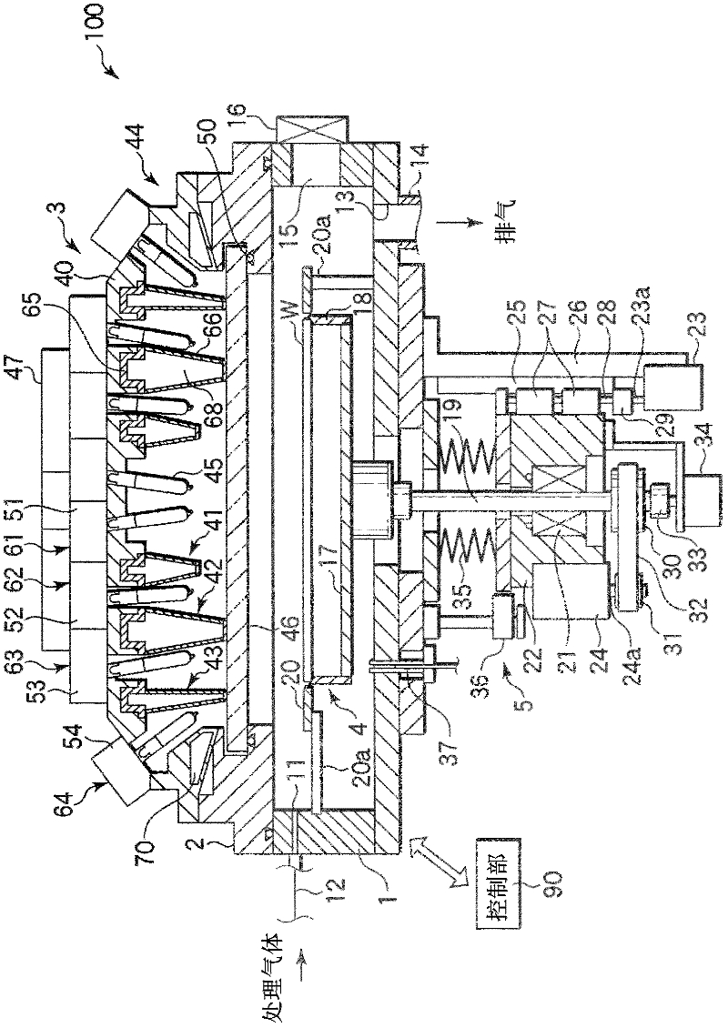
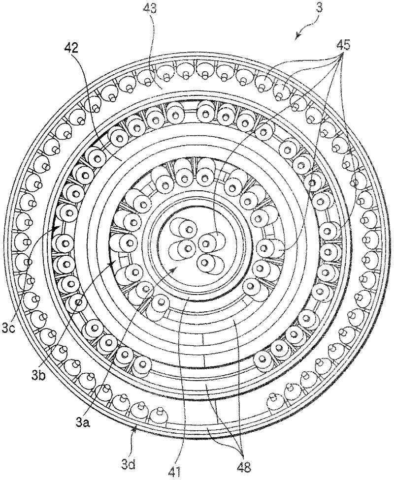
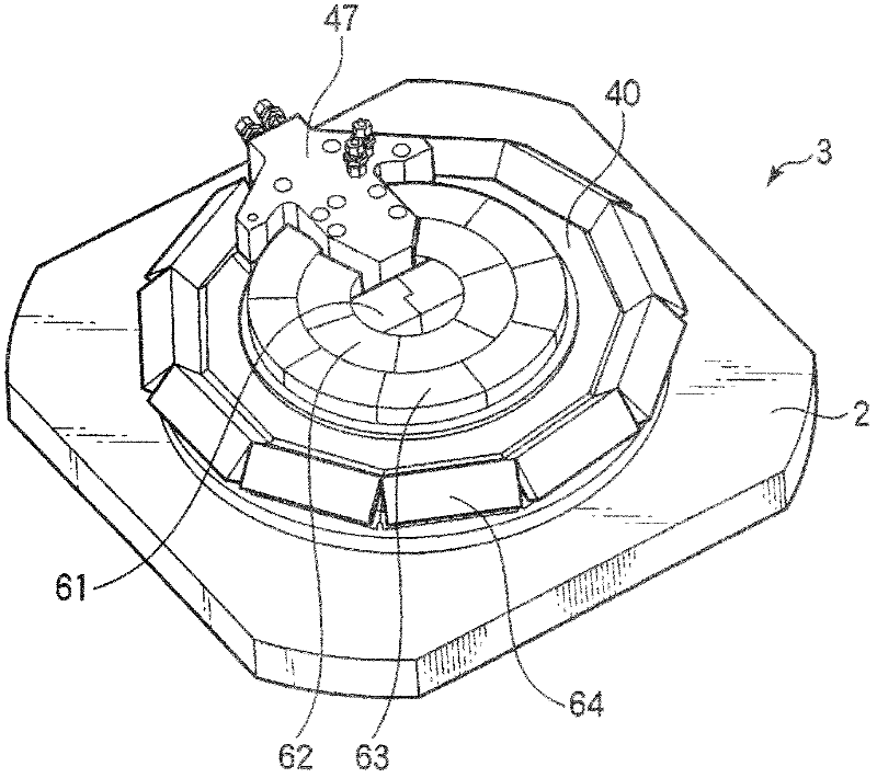
[0035] figure 1 is a cross-sectional view of an annealing apparatus showing a first embodiment of the heat treatment apparatus of the present invention, figure 2 is a bottom view showing its lamp assembly, image 3 It is a perspective view showing the appearance of the lamp unit, Figure 4 It is a perspective view showing a state where a lamp module is detached from a lamp unit, and FIG. 5 is a schematic view showing a configuration of each lamp module.

[0036] The annealing apparatus 100 includes the following main components: a processing container 1, which specifies a processing space for processing a wafer W as a substrate to be processed; a cover 2, which is fixed on the upper end of the processing container 1, and is ring-shaped; a lamp assembly 3, It is supported by a cover 2, and is provided with a plurality of halogen lamps; a wafer supporting part 4, which supports a wafer W in the processing container 1; Supported wafer W.

[0037] A gas introduction hole 11 i...

no. 2 approach

[0066] Next, a second embodiment of the present invention will be described.

[0067] The purpose of this embodiment is to protect the power supply terminal 57 of the halogen lamp 45 . When the halogen lamp 45 is turned on during the annealing process, the heat supply terminal 57 is heated through the heat supply terminal 57 . When the temperature of the power supply terminal 57 exceeds 350° C. by heating, the Mo foil used as a conductor is rapidly oxidized and disconnected. Therefore, in the present embodiment, cooling of the power supply terminal 57 and light shielding from the halogen lamp 45 to the power supply terminal 57 are performed.

[0068] Figure 12 is a partial sectional view showing a lamp unit of an annealing apparatus according to a second embodiment of the present invention, Figure 13 is a sectional view showing its main parts, Figure 14 It is a perspective view showing the mounting state of the halogen lamp. In the lamp unit 103 of the present embodime...

no. 3 approach

[0075] Next, a third embodiment of the present invention will be described.

[0076] In the lamp assembly, the sealing ring installed between the light transmission plate and the cover is provided close to the halogen lamp 45, so in the lamp assembly by the heat generated from the halogen lamp, and also by being irradiated by light emitted from the halogen lamp, Thermal deformation and melting may occur due to heating. Therefore, in this embodiment, the structure for protecting such a seal ring will be mainly described.

[0077] Figure 15 is a cross-sectional view showing main parts of an annealing apparatus according to a third embodiment of the present invention, Figure 16 It is a sectional view showing the light transmission plate supporting part of the annealing apparatus of the third embodiment. The annealing apparatus of the present embodiment includes a lamp unit 203 having a light transmission plate 46 ′ formed with a flange portion (step portion) 46 a. The flang...


PUM


Abstract

Disclosed is a heat treatment apparatus (100) which comprises: a treatment chamber (1) in which a wafer (W) is contained; a substrate supporting unit (4) for horizontally supporting the wafer (W) within the treatment chamber (1); and a lamp unit (3) that is provided above the treatment chamber (1). The lamp unit (3) comprises: a base member (40); a plurality of lamps (45) that are provided on the lower surface of the base member (40) with the front ends facing down; a plurality of ring-shaped reflectors (41, 42, 43) that are concentrically provided on the lower surface of the base member (40) so as to project downward; and a cooling head (47) for supplying a cooling medium into the reflectors (41, 42, 43). At least some of the plurality of lamps (45) are arranged along the reflectors (41, 42, 43), and cooling medium channels (68), each of which is composed of a ring-shaped space, are provided within the reflectors (41, 42, 43) in the arrangement direction of the reflectors.

Description

technical field [0001] The invention relates to a heat treatment device capable of rapid heating and rapid cooling of a substrate. Background technique [0002] In the manufacture of semiconductor devices, various heat treatments such as film formation treatment, oxidation diffusion treatment, modification treatment, and annealing treatment are performed on a semiconductor wafer (hereinafter simply referred to as wafer) as a substrate to be processed. Among these heat treatments, especially annealing treatment for removing strain after film formation and annealing treatment after ion implantation, the temperature tends to be raised and lowered at a high speed from the viewpoint of improving throughput and suppressing diffusion to a minimum. As such a heat treatment apparatus capable of rapidly raising and lowering the temperature, an apparatus using a lamp typified by a halogen lamp as a heating source is often used. [0003] As a heat treatment device using such a lamp, a ...

Claims


Application Information

Patent Timeline
Patent Type & Authority Applications(China)
IPC IPC(8): H01L21/26H01L21/205H01L21/31
CPCH01L21/68792H01L21/67115H01L21/205H01L21/26
Inventor 小松智仁釜石贵之山崎良二
Owner TOKYO ELECTRON LTD
Why Eureka
Try Eureka