
Method for producing cogged wheel with herringbone gearing and method and device for generating control data

A technology of herringbone teeth and control data, applied in the related fields, can solve the problems of increased load in the boundary area, long processing time, less cutting volume, etc., and achieve the effect of reducing the load, increasing the strength of the teeth, and increasing the volume.

Active Publication Date: 2012-04-18
DECKEL MAHO PFRONTEN GMBH
View PDF8 Cites 8 Cited by
  • Summary
  • Abstract
  • Description
  • Claims
  • Application Information

AI Technical Summary

Problems solved by technology

However, this method is also more costly and requires longer machining times due to the fact that the tooth flanks are machined separately, followed by machining the grooves with a smaller milling cutter, resulting in less cutting volume
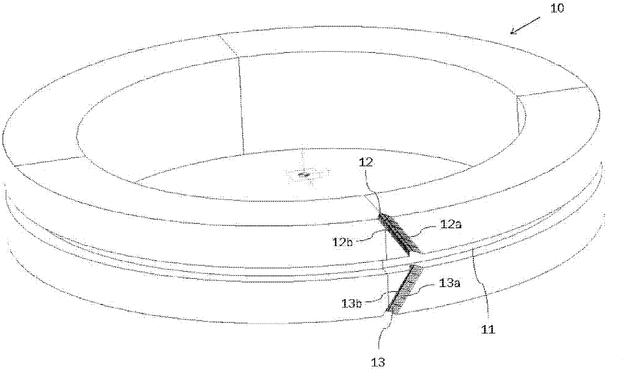
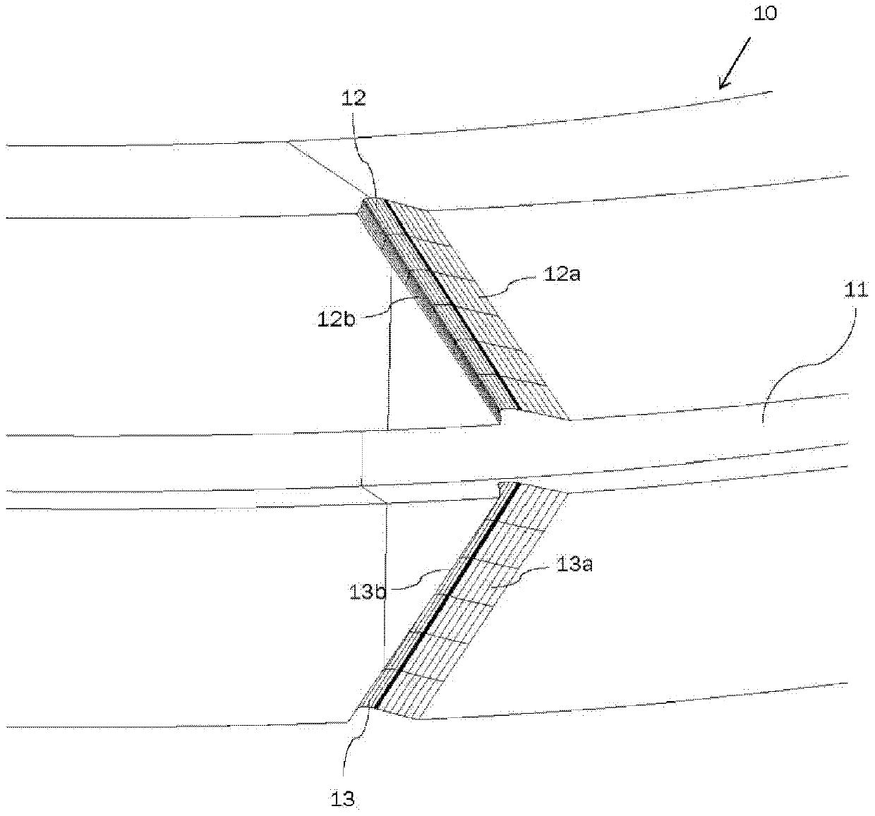
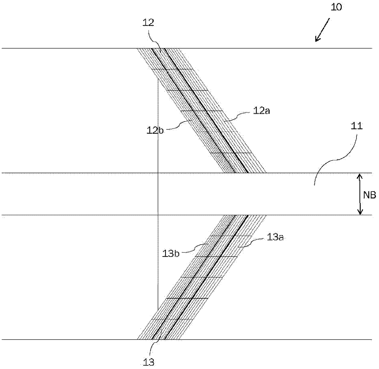
In addition, since there is no rolling area available at the central end of the chevron teeth, the load on the border area of ​​the tooth flanks 12a, 12b, 13a and 13b close to the groove 11' increases

Method used


Image

  • Method for producing cogged wheel with herringbone gearing and method and device for generating control data
  • Method for producing cogged wheel with herringbone gearing and method and device for generating control data
  • Method for producing cogged wheel with herringbone gearing and method and device for generating control data

Examples


Embodiment Construction

[0055] Preferred embodiments of the present invention are described below in conjunction with the accompanying drawings, however, the embodiments described here are only used to explain the present invention, not to limit the present invention. The invention is defined by the claims. Equivalent and / or similar features in the embodiments are indicated by the same reference numerals in the figures.

[0056] In the prior art, in order to separately calculate the geometric models of the workpiece with the gear, the gear and the tooth surface, for example, through a CAD system, the necessary gear information data should be predefined and / or determined. Therefore, in particular, the following data are necessary to calculate the mathematical or numerical model of the tooth flank:

[0057] Data representing the shape and dimensions of the entire workpiece before and / or after machining (e.g. data used to calculate unmachined part geometry and / or machined part geometry, respectively, a...


PUM


Abstract

The invention relate to a method which is used to generate a cogged wheel with a herringbone gearing 10. The invention includes a device for producing control data comprising a geometry modeling unit, a numerically controlled, 4-axle machine tool comprising a control data producing device a computer program product comprising a computer program for executing a method for producing control data. A process and an apparatus for generating control data, wherein a first tooth flank geometry 12b is determined which corresponds to a geometry of a first tooth flank of the herringbone gearing, a second tooth flank geometry 13b is determined which corresponds to a geometry of a second tooth flank of the herringbone gearing, a transition section geometry 14b is determined which corresponds to a geometry of a transition section between the first tooth flank and the second tooth flank, an overall tooth flank geometry 12b, 13b, and 14b is determined which comprises the first tooth flank geometry 12b, the transition section geometry 14b and the second tooth flank geometry 13b, and the control data is generated based on the overall tooth flank geometry 12b, 13b, and 14b and machining paths are indicated, each extending transversely to the profile direction of the tooth flanks and along the first tooth flank geometry 12b, the transition section geometry 14b and the second tooth flank geometry 13b.

Description

technical field [0001] The invention relates to a method for producing gears with herringbone teeth, on a numerically controlled machine tool comprising at least four axes, by continuously moving the milling tool of the machine tool along a machining path relative to the workpiece on the basis of control data to mill the workpiece A gear with herringbone teeth can be generated by means of a method. Specifically, the milling cutter can be an end mill, and the CNC machine tool can be a milling machine, a general-purpose machine tool or a machining center. The method comprises: on the basis of the profile of a tooth, generating control data, the control data comprising path data, the control data being usable for guiding the milling cutter of the machine tool along the machining path, and for using the The milling tool mills the workpiece on the machine tool, wherein the milling tool can be continuously guided along a machining path represented by the path data. [0002] Further...

Claims


Application Information

Patent Timeline
Patent Type & Authority Applications(China)
IPC IPC(8): B23F7/00
CPCG05B19/40937G05B19/186Y10T29/49462Y10T74/19953Y10T409/100159Y02P90/02
Inventor 约瑟夫·纽麦尔托马斯·劳切比勒尤文卡斯滕·汉森
Owner DECKEL MAHO PFRONTEN GMBH
Learn More