Generation system for rail cars

A technology for power generation systems and railway vehicles, which can be used in railway vehicles, electric braking systems, control systems, etc., and can solve problems such as heavy workload.

Inactive Publication Date: 2012-04-18
HITACHI LTD
View PDF5 Cites 5 Cited by
  • Summary
  • Abstract
  • Description
  • Claims
  • Application Information

AI Technical Summary

Problems solved by technology

[0015] For the communication components between the system integrated control unit and the engine, in most cases, the interface and communication components of the engine control device are different from manufacturer to manufacturer. In addition, even if the interface and communication components are the same, the information transmission sequence or information transmission method is different in most cases. , so design the communication parts between the system integrated control unit and the engine according to each corresponding case, resulting in a heavy workload

Method used


Image

  • Generation system for rail cars
  • Generation system for rail cars
  • Generation system for rail cars

Examples


Embodiment Construction

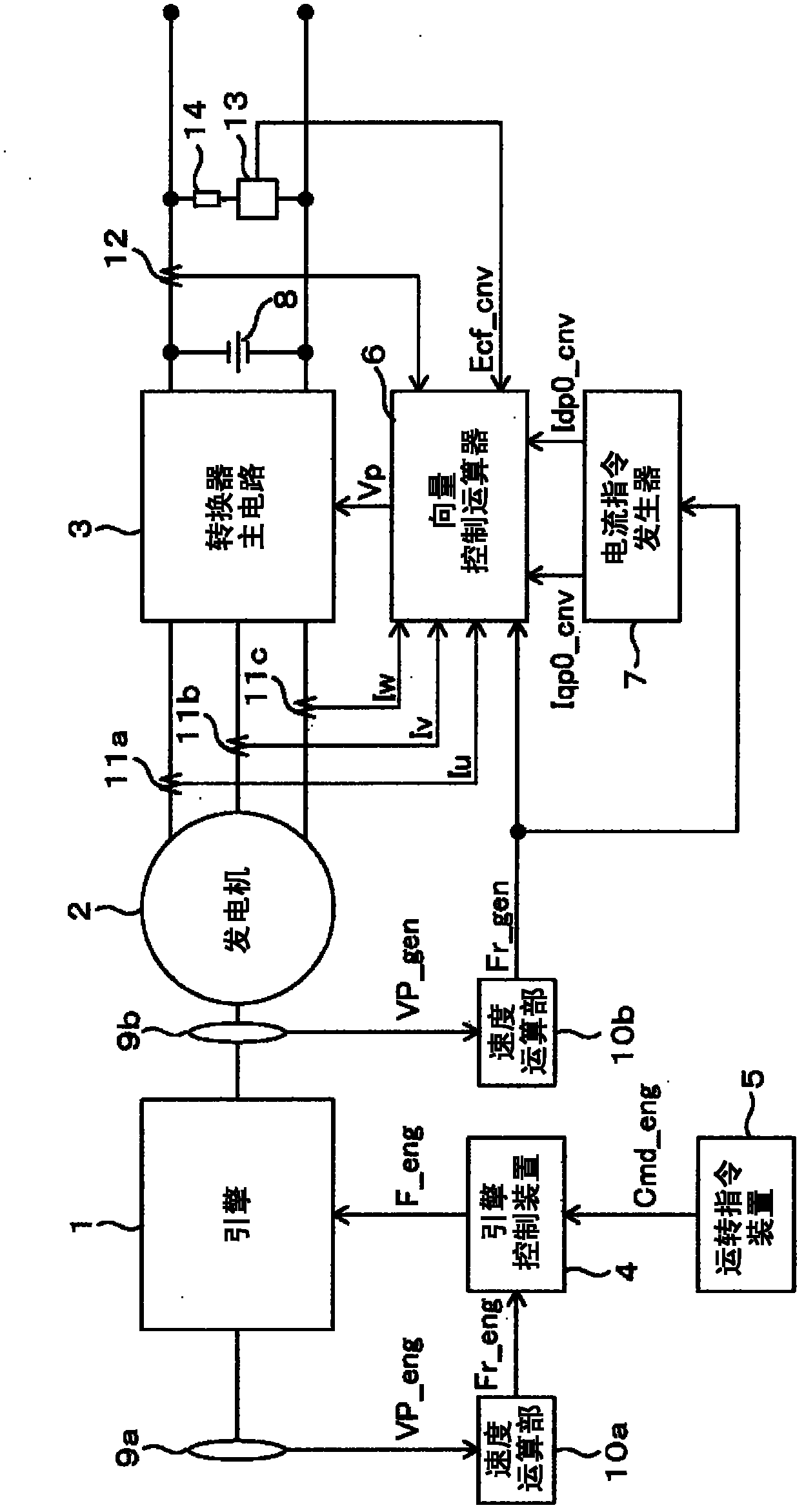
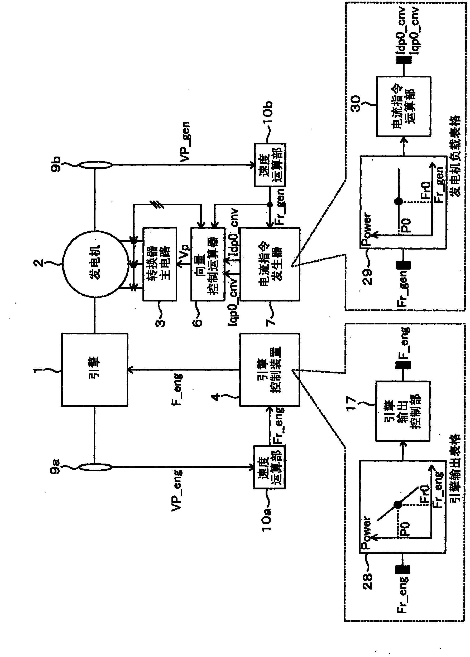
[0067] figure 1 It is a figure which shows the equipment structure of one Embodiment in the railway vehicle engine control system of this invention.

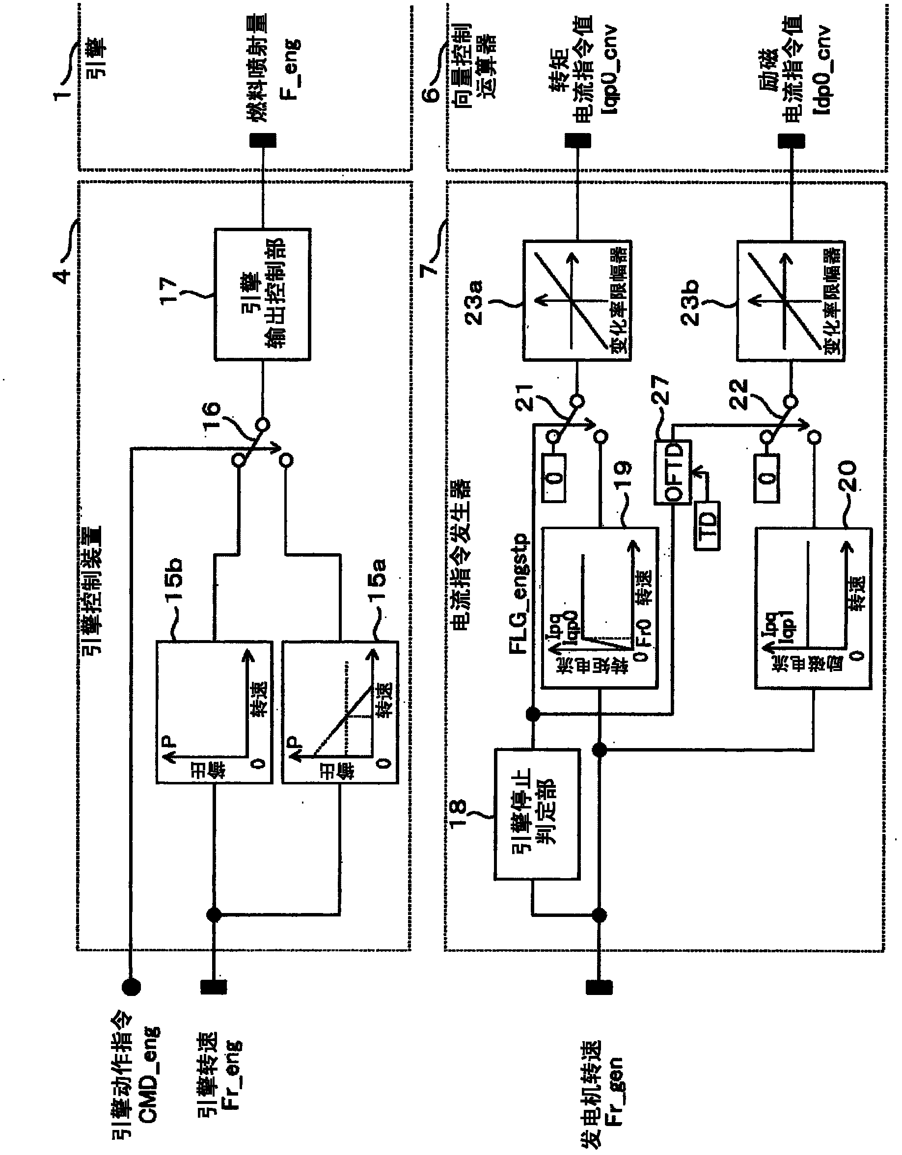
[0068] The engine 1 outputs shaft torque based on a fuel injection amount command F_eng from the engine control device 4 . The generator 2 is connected to the engine 1 via a drive shaft, and takes the shaft torque of the engine 1 as input, converts it into three-phase alternating current, and outputs it.

[0069] The converter main circuit 3 receives the three-phase AC power output from the generator 2 as input, converts it into DC power, and outputs it. The DC side voltage of the converter main circuit 3 is adjusted to a voltage value within a certain range by a DC voltage source such as a power storage device or a power generation system (not shown).

[0070] The vector control calculator 6 uses the three-phase AC currents Iu, Iv, and Iw detected by the AC current detectors 11a, 11b, and 11c, the rotational speed signal Fr_...


PUM


Abstract

The present invention provides a generation system for rail cars which controls the operation or generation output of an engine generator without the need for electric transmission of control information between an engine control system and a generation control system. An engine control device configured to control power from the engine recognizes an engine rotation speed signal calculated by a speed calculation section based on information from a rotation detector attached to the engine. The engine control device thus controls the engine power in accordance with the engine rotation speed signal. Furthermore, a generator control device configured to control a generation output from a generator recognizes a generator rotation speed signal calculated by the speed calculation section based on information from a rotation detector provided in the generator. The generator control device thus controls the generation output in accordance with the generator rotation speed signal. Hence, engine generation control can be implemented without the need to transmit information between engine control and generator control.

Description

technical field [0001] The present invention relates to a power generation system of a railway vehicle, and more particularly to a technology of a power generation system of a railway vehicle that controls the operation of an engine generator or generates electricity without exchanging electrical control information between the engine control system and the power generation control system. Background technique [0002] Since railway vehicles run on rails with iron wheels, they are characterized in that their running resistance is smaller than that of automobiles. Especially in recent electric railway vehicles, the main motor acts as a generator to obtain braking force during braking, and at the same time, regenerative brake control is performed to return the electric energy generated by the main motor during braking to the overhead wire as a power supply for other vehicles. Accelerated energy reuse. Electric railway vehicles equipped with such regenerative brakes can run wi...

Claims


Application Information

Patent Timeline
Patent Type & Authority Applications(China)
IPC IPC(8): B60L11/14H02P9/00B60L50/15B60L50/16
CPCB60L2200/26Y02T10/643H02P9/04B60L7/14H02P9/48B60L11/1803B60L2240/427Y02T10/7005B60L2240/421Y02T10/70B60L2240/443B60L15/025B60L2240/429B60L2240/441B60L50/51Y02T10/64B60W10/08
Inventor 岛田基巳丰田瑛一
Owner HITACHI LTD
Why Eureka
Try Eureka