
Bionic engine, and implementation method thereof

A realization method and engine technology, applied in machine/engine, non-variable engine, mechanical equipment, etc., can solve the problems of incomplete scavenging, small relative sliding amount, loss of control, etc.

Inactive Publication Date: 2012-04-18
谢本武
View PDF0 Cites 0 Cited by
  • Summary
  • Abstract
  • Description
  • Claims
  • Application Information

AI Technical Summary

Problems solved by technology

[0008] (2) The force receiving and receiving during the expansion stroke is not ideal. When the piston compresses to the top dead center, theoretically it is the beginning of ignition and expansion.
Expansion work cannot be effectively utilized
[0009] 3. Since the initial temperature of expansion reaches 2900K, it is very easy to produce NOx, and because of the uneven distribution of oxidant
Directly cause more than 4% fuel loss, become CO and soot emissions to pollute the environment
[0010] 4. Working fluid filling (filling quantity) coefficient ψ = 0.7-0.9, coupled with incomplete scavenging, complex mechanism, low space utilization, many parts and high precision requirements, and random coordination is difficult
[0011] 5. During the ventilation process, the temperature of the working medium changes sharply, and the frequency of the temperature change of the flow field is high, resulting in large creep of the cylinder liner and short engine life
[0012] 6. There are strict requirements on fuel, limited by the seasonal and geographical environment, and the scope of use is narrow
[0013] 7. The effective work output of the piston is intermittent, that is, the utilization rate of the working time is less than 15%.
However, it works at high temperature, the temperature gradient is large, the linear dimension difference of matching parts is large, the expansion is different, the curved surface is matched at many points, and the sealing is difficult, resulting in air leakage between flow fields, loss of pressure, and loss of control
Unlike gear meshing, single pitch diameter, conformal curved surface, less relative sliding, and press 1 / 2 n The positive pressure of the recursive principle is compensated by mutual elastic deformation, but this kind of body sealing is an insurmountable obstacle
Although the gas turbine also operates in one direction as a rotating working medium, the flow field (the place where the working medium works or accumulates) has many and complicated components, requires high-temperature heat-resistant alloys, is difficult to manufacture, has high noise, and lower thermal efficiency. Part of the kinetic energy, working fluid potential energy and internal energy are basically not used

Method used


Image

  • Bionic engine, and implementation method thereof
  • Bionic engine, and implementation method thereof
  • Bionic engine, and implementation method thereof

Examples


Embodiment 1

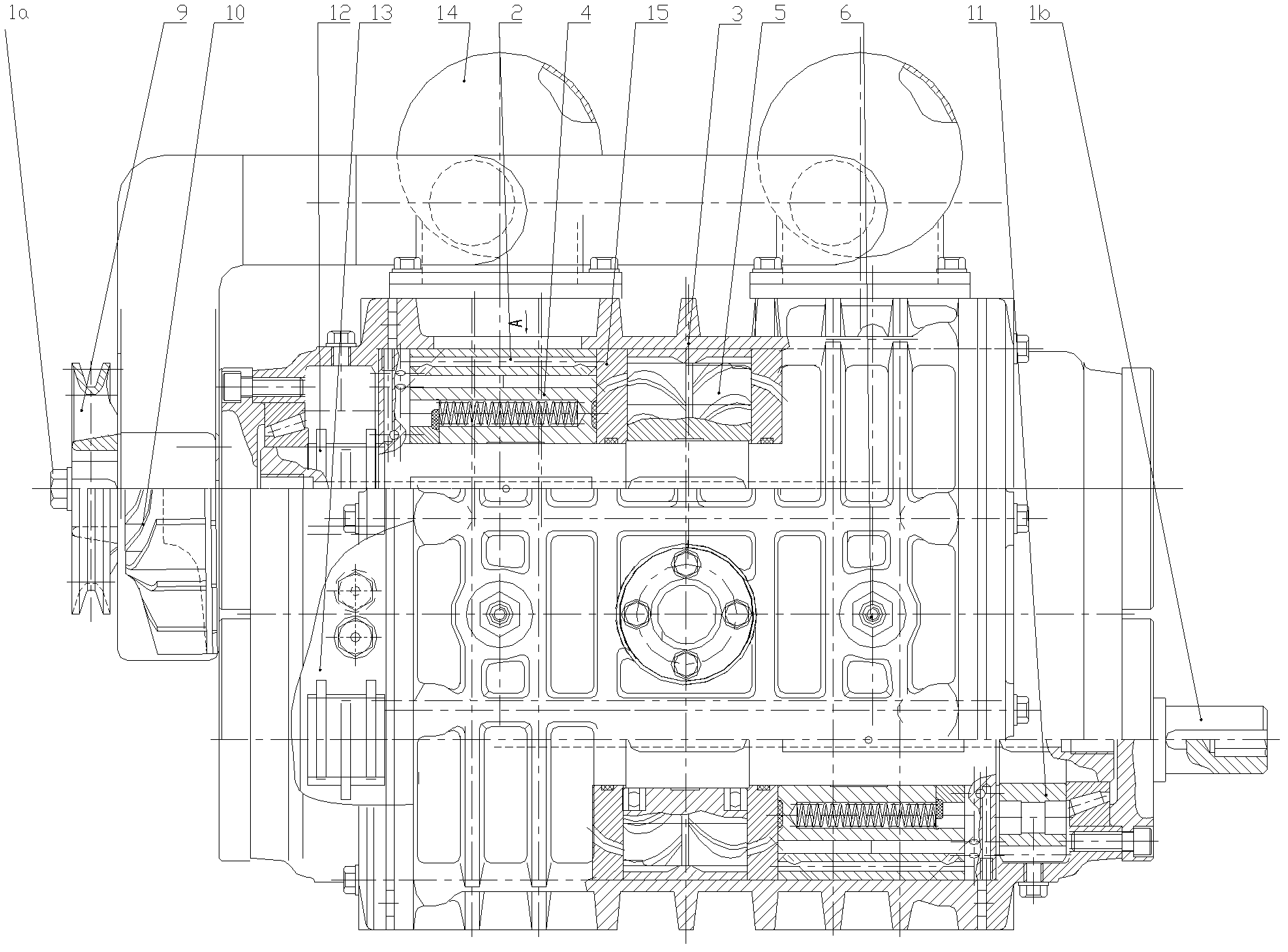
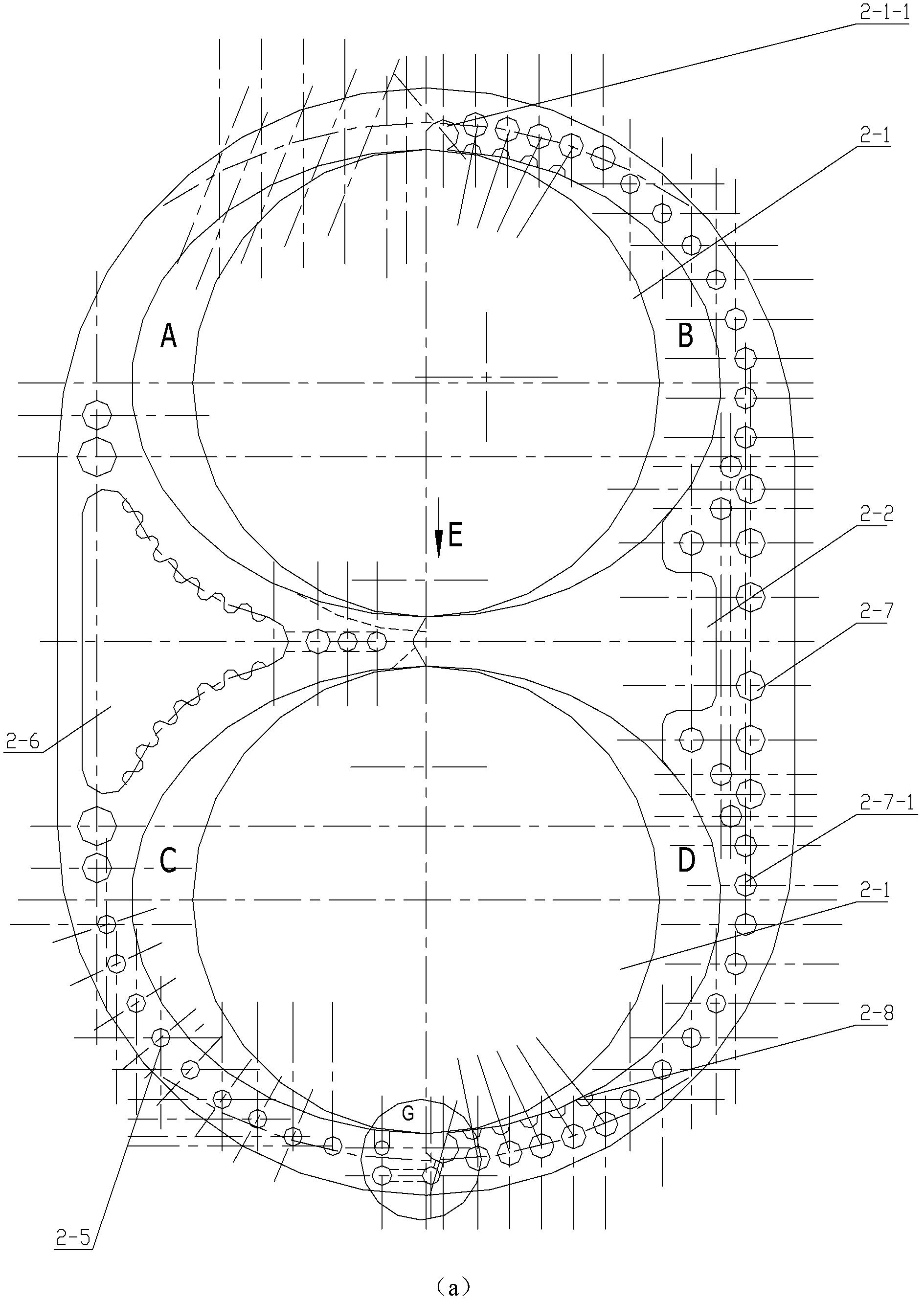
[0068] see Figure 1-7 , a bionic engine, the whole machine includes two sets of double The rotor stator pair and the turbine pair in the middle; the main shaft includes the input shaft and the output shaft, and the main shaft runs through the rotor stator pair and the turbine pair in parallel; the compressor wheel, the cam for driving the oil pump, and the front and rear parts are installed on the input shaft. Rotor, turbine and synchronous gear, a set of corresponding front and rear parts are installed on the output shaft Energy rotor, turbine and synchronous gear, the output shaft extends out to the output end, and the output shaft and input shaft work synchronously through the synchronous gear;

[0069] The body of the bionic engine is provided with a pressure accumulator;

[0070] pair Energy rotor stator pair includes energy stator and rotor;

[0071] each double In the rotor-stator pair, The stator is equipped with two symmetrical cavities up and down, and...


PUM

PropertyMeasurementUnit
Diameteraaaaaaaaaa

Abstract

The invention discloses a bionic engine and an implementation method thereof. The whole machine comprises two sets of double energy rotor and stator pairs on front and rear parts, and a worm gear pair on the middle part; a main shaft comprises an input shaft and an output shaft, and passes through the rotor and stator pairs and the worm gear pair parallelly; the input shaft is provided with a gas compression wheel, a cam used for driving an oil pump, front and rear energy rotors, a worm wheel and a synchromesh gear; the output shaft is provided with one corresponding set of front and rear energy rotors, a worm wheel and a synchromesh gear; an output end is extended out of the output shaft, and the output shaft and the input shaft do work synchronously through the synchromesh gears; and in each double energy rotator and stator pair, an energy stator is provided with two cavities which are symmetrical to each other in the vertical direction, two rotors are arranged in the two cavities respectively so as to form main flow fields A, B, C, and D, and the tail ends of the main flow fields B and D are provided with crossed control channels. The bionic engine has a unique structure and is high in thermal efficiency and is a revolutionary engine.

Description

technical field [0001] The invention belongs to the technical field of engines, and relates to a bionic engine and a realization method thereof. Background technique [0002] There are many types of modern engines, and they also occupy various fields. Here, only the piston engine with high thermal efficiency is taken as an example, and the gasoline engine is used as a reference engine as follows: [0003] To measure the pros and cons of an engine, it is mainly thermal efficiency, which is the ratio of the effective work output by the engine to the total work produced by the working medium. The gasoline engine only has η=0.22-0.3, and the random sampling data of practical machines is 3-5% lower than this value , In terms of environmental impact, a 100KW engine emits 600kg of CO and 40kg of NO into the atmosphere within a year, and smoke and dust account for 3-8% of the exhaust. [0004] Influencing factors: [0005] 1. Cooling energy consumption is about 30%, the highest ca...

Claims


Application Information

Patent Timeline
IPC IPC(8): F01D1/02F02C3/14F02C3/20F02C3/32
Inventor 谢本武
Owner 谢本武
Learn More