Improved bone resector

A technology of bone, cutting head, applied in the field of surgical tools for bone removal, can solve the problem of surgeon's hands and fingers fatigue, white fingers

Active Publication Date: 2012-04-18
ORTHOFIX SRL
View PDF8 Cites 3 Cited by
  • Summary
  • Abstract
  • Description
  • Claims
  • Application Information

AI Technical Summary

Problems solved by technology

This low frequency vibration is uncomfortable and can lead to more rapid fatigue of the surgeon's hands and fingers, prolonged use of this action can even create problems such as "white fingers"

Method used


Image

  • Improved bone resector
  • Improved bone resector
  • Improved bone resector

Examples


Embodiment Construction

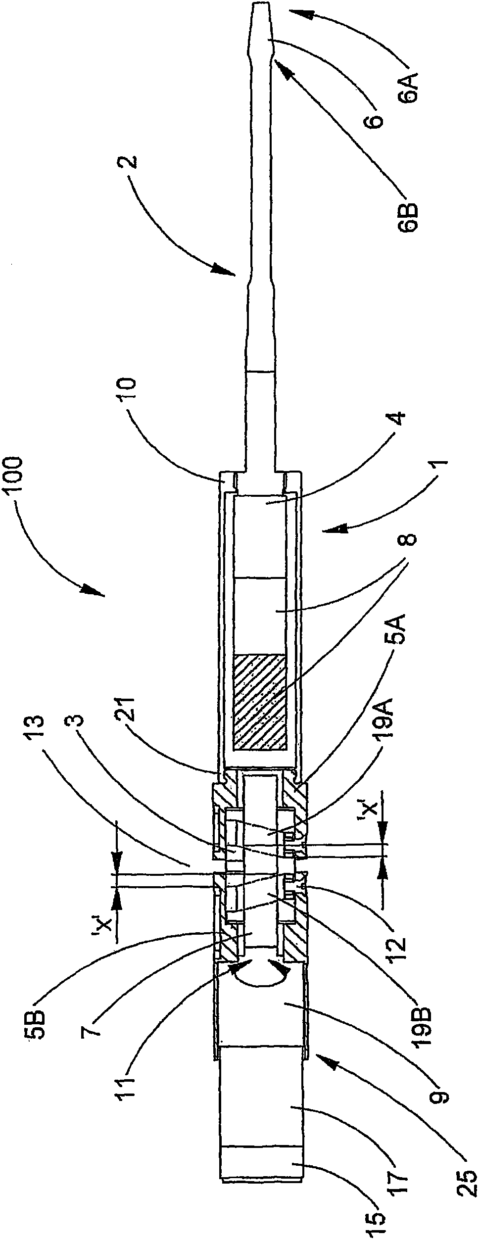
[0062] In the following, see the accompanying drawings, and in particular Figure 1A , the acoustic system 1 of the first osteotomy tool 100 includes a longitudinal mode ultrasonic transducer 8 (usually including stacked piezoelectric elements), the ultrasonic transducer 8 is connected to a strip-shaped replaceable The blade part 2. The blade part 2 has at its distal end a cutting head 6 provided with one or more lateral cutting edges. (cutting edge not in Figure 1A is specifically shown in , but may generally include serrations arranged in an array in a desired geometry. The present invention is adaptable to most or all existing forms of osteotome blade geometries).

[0063] The particular tool 100 shown generates ultrasonic vibrations in its blade portion 2 with a maximum longitudinal displacement amplitude of 80-140 μm at the distal end 6A of the cutting head 6 . The ultrasonic transducer 8, the arm 4 and the blade part 2 are adjusted so that the distal end 6A is at the ...


PUM


Abstract

A bone resector tool (100) comprises an ultrasonic transducer (8), typically generating longitudinal mode vibrations at around 40 kHz, and having an elongate blade portion (2) mounted thereto. The transducer (8) and blade portion (2) are mounted to a rotatably- drivable converter element (3). Rotation of the converter element (3) produces reciprocal longitudinal motion of the transducer (8) and blade portion (2). A counterweight (5B) is also mounted to the converter element (3), moving exactly out of phase with the transducer (8) and blade portion (2), such that a centre of mass of the whole system is stationary, reducing vibration of the tool (100) in a user's hand. The peak velocity due to the ultrasonic vibrations of a distal tip (6A) of the blade portion (2) is up to seven times greater than its peak velocity due to the reciprocal longitudinal motion. This permits rapid, low-effort cutting of bone with easy removal of cut debris and minimal consequent necrosis.

Description

technical field [0001] The present invention relates to a surgical tool for cutting cortical bone and cancellous bone. More particularly but not limitedly, the present invention relates to a surgical tool for bone resection in minimally invasive surgical techniques. Background technique [0002] For example, it is known from our UK Patent Application No. GB2420979A to cut cortical and cancellous bone during surgery using an ultrasonically excited instrument having a cutting edge with a sawtooth profile. [0003] Conventional powered oscillating saws with sharp tooth profiles and lateral tooth offsets are also effective in many situations. Increasingly, however, joint replacement surgery therein is often performed through a reduced size incision to reduce soft tissue damage. Although this has obvious benefits in terms of postoperative healing, it requires high skill and dexterity on the surgeon's part to achieve the correct bone surface geometry for the implant site to mane...

Claims


Application Information

Patent Timeline
Patent Type & Authority Applications(China)
IPC IPC(8): A61B17/16A61B17/32
CPCA61B17/32002A61B17/320068A61B2017/320072A61B17/1664A61B2017/320028A61B2017/320077A61B2017/320089
Inventor M·J·R·扬
Owner ORTHOFIX SRL
Why Eureka
Try Eureka