
Method for pumping dregs through earth pressure balance shield

A technology of earth pressure balance and shield pump, which is applied in earthwork drilling, mining equipment, tunnels, etc., can solve the problems of reduced construction efficiency, high track requirements, and reduced excavation efficiency, so as to improve excavation work efficiency, reduce safety risks, The effect of reducing equipment investment

Active Publication Date: 2012-04-25
CCCC SECOND HARBOR ENG
View PDF4 Cites 28 Cited by
  • Summary
  • Abstract
  • Description
  • Claims
  • Application Information

AI Technical Summary

Problems solved by technology

Although the use of rail slag trucks to transport muck has many advantages, such as no requirements on the properties of the muck, and is suitable for earth pressure balance shield muck transportation under any geological conditions, it still has many shortcomings: first, for limited space When the subway tunnel or track laying is used to transport muck, the excavation of the first ring often needs to be stopped halfway to replace the muck truck, and the two trains entering and leaving take up the excavation time, which reduces the excavation efficiency; the temporary track system for battery cars is generally easy to set up and frequent Derailment will also reduce construction efficiency
Second, heavy-duty transportation of muck requires a large-tonnage battery car, and vertical transportation requires a gantry crane with a large lifting capacity. The cost of equipment purchase is high
Third, the horizontal transportation of muck has high requirements on the track. For example, marshalled trains for heavy-duty transportation of muck are prone to safety accidents such as slipping and derailment; vertical transportation takes a long time, and there are many safety hazards in vertical lifting
Fourth, in special circumstances such as the initial stage of shield tunneling, limited site space, or gushing during the excavation process, the adaptability of track muck transportation is poor, and the construction efficiency is reduced by double or even several times.

Method used


Image

  • Method for pumping dregs through earth pressure balance shield

Examples


Embodiment Construction

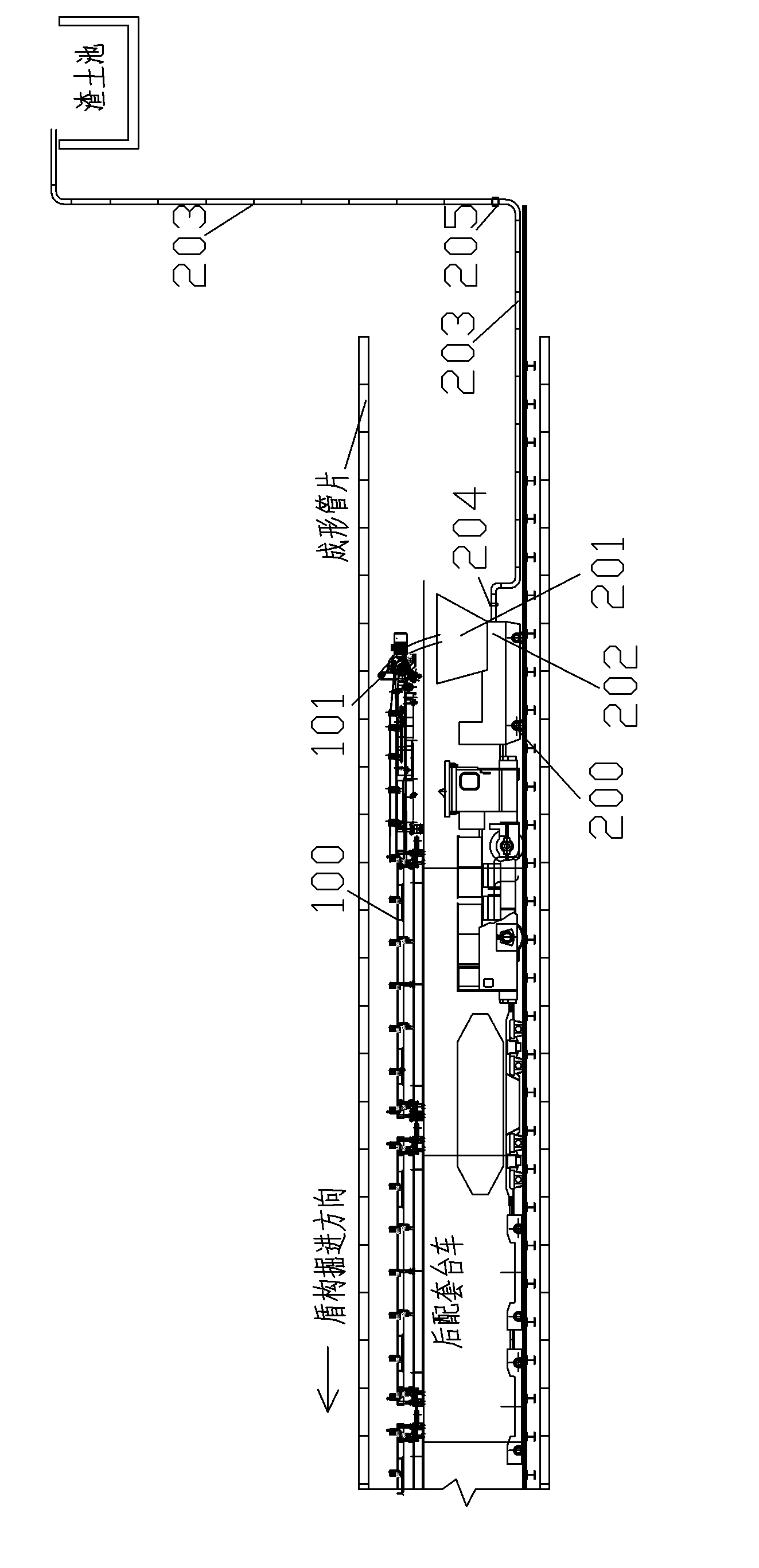
[0022] Realize the system composition of the inventive method as figure 1 As shown, it includes the soil bin (not shown in the figure) supporting the shield machine. The front end of the soil bin is provided with a vibrating screen (used to filter stones). It is an existing structure; The belt conveyer 100, the discharge port 101 of the muck belt conveyer 100 is lowered to the muck pump truck 200, and the dreg pump truck 200 is provided with a pump hopper 201, and the discharge of the pump hopper 201 is connected to the Unicom muck pump 202, The output of the muck pump 202 is connected to a communication pipeline 203, and a water injection ring 204 is connected to the pipeline 203. The water injection ring 204 is a nozzle arranged on the pipeline wall, which can inject high-pressure water into the pipeline to lubricate the muck in the pipeline. A control valve 205 is connected to the pipeline 203 .

[0023] According to the geological conditions, use foam, polymer, bentonite...


PUM

PropertyMeasurementUnit
Slumpaaaaaaaaaa

Abstract

The invention discloses a method for pumping dregs through an earth pressure balance shield. During the process of mining a tunnel through a shield method, stone blocks in the dregs excavated by a shield machine are filtered, then an additive is added for performing flow plasticity improvement on the dregs, the slump of the dregs after improvement is 165-185mm, and a dreg pump and a pipeline are utilized for pumping the dregs to the outside; and the additive is one or the combination of more than one of water, a foaming agent, a high polymer and bentonite. By adopting the method, the transportation of the dregs can be simultaneously performed during tunneling and the tunneling work efficiency is effectively improved; during the initial stage of the shield, as the pumping of the dregs is realized, a soil outlet well does not need to be additionally increased and the normal tunneling can be achieved during the initial state; when the tunnel spews, the dregs can be continuously pumped to the outside and the work efficiency of clearing slurry in the tunnel can be greatly improved.

Description

technical field [0001] The invention belongs to the construction technology of shield excavation underground tunnels, and in particular relates to a technology for conveying dregs generated during shield excavation during shield excavation tunnel construction. Background technique [0002] The shield tunneling method is a construction method in which special machines for underground tunnels are used to build tunnels below the ground. According to the structural characteristics and excavation methods of the shield machine, there are many classifications, among which the earth pressure balance shield method and the mud-water balance shield method are the most commonly used, and the slag discharge methods of the two are also quite different. [0003] Muddy water shield excavation is mainly based on soft soil, sandy and other weak strata. It uses muddy water of different concentrations in the two pipelines entering and leaving the muddy water warehouse to replace the soil in the...

Claims


Application Information

Patent Timeline
IPC IPC(8): E21D9/12
Inventor 张鸿翟世鸿董汉军吴忠善鞠义成石磊谭啸峰陈斌孙金锁徐海江徐国平邓鹏胡敏润
Owner CCCC SECOND HARBOR ENG
Learn More