LED (Light-Emitting Diode) illuminating device and radiating structure thereof

A technology of LED lighting and heat dissipation structure, which is applied to lighting devices, cooling/heating devices of lighting devices, lighting and heating equipment, etc. Promote large-scale promotion and application, good heat dissipation effect and fast startup speed

Inactive Publication Date: 2012-04-25
GUANGZHOU ZHONGHENG OPTOELECTRONICS TECH
View PDF0 Cites 1 Cited by
  • Summary
  • Abstract
  • Description
  • Claims
  • Application Information

AI Technical Summary

Problems solved by technology

The disadvantages of using realistic light sources are:
[0003] 1. The lamp tube is easily broken during transportation and installation, which brings many disadvantages to the construction;
[0004] 2. The high breakage rate of the lamp tube increases the cost of use; 3. The life of the actual light source is generally relatively short, and the lamp tube needs to be replaced frequently. Generally, the continuous working life of incandescent lamps is about 1200 hours, and the continuous working life of fluorescent lamps and halogen lamps is 3000 hours. about hours;
[0005] 4. The current lighting source is not suitable for the working conditions of frequent switching of lighting lamps, especially the rectifier of fluorescent lamps is easily damaged, and the cost of frequent replacement of lamp tubes and maintenance is high;
[0006] 5. For fluorescent lighting, it needs high voltage to start, and it takes a certain time to start to light, low efficiency, high power consumption, and mercury in fluorescent lamps, which pollutes the environment to a certain extent, which is also a well-known disadvantage.
Generally, low-power LEDs use PCB boards as substrates. PCB boards are generally made of organic resin and other raw materials, and are directly wired on the PCB board without heat dissipation treatment. This kind of PCB board has poor thermal conductivity. When using LEDs that generate heat , the heat is not easy to dissipate, causing the junction temperature of the LED to rise, which directly affects the light efficiency of the LED, accelerates its light decay, and reduces the service life of the LED
In recent years, some aluminum substrates have been used as LED substrates, which are conducive to the heat dissipation of LEDs. However, due to the high price of aluminum substrates, they are not suitable for low-power LEDs. Due to cost factors, they cannot be widely used in the market.
For high-power LEDs, it is generally used to print circuits on aluminum substrates, and then dissipate heat through an external heat sink. Since there is an insulating layer on the aluminum substrate, the thermal resistance is also large, and this method cannot achieve the best heat conduction effect.
[0010] After retrieving Chinese patents, there are some inventions related to the application of LED lighting, but their connection arrangement is different from the present invention, and there is no heat dissipation structure, and the realized work efficiency, function and service life cannot meet the requirements of LED in the market. Vigorously popularize and apply, and cannot solve the technical problems existing in existing lighting devices

Method used


Image

  • LED (Light-Emitting Diode) illuminating device and radiating structure thereof
  • LED (Light-Emitting Diode) illuminating device and radiating structure thereof
  • LED (Light-Emitting Diode) illuminating device and radiating structure thereof

Examples


Embodiment Construction

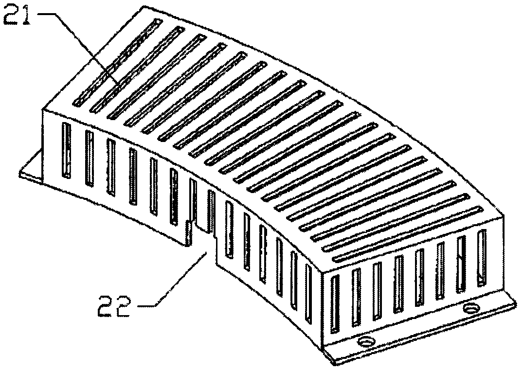
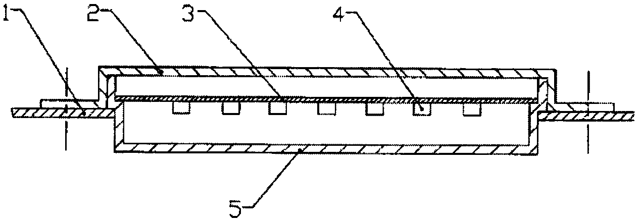
[0035] attached figure 1 It shows the structure diagram of the best embodiment of the LED lighting device of the present invention.

[0036] Attached below figure 1 Further describe the content and working principle of the present invention in detail.

[0037] Marked in the figure: 1. Connection plate, 2. Protective cover plate, 3. Substrate, 4. LED particles, 5. Light-transmitting plate, 6. Copper clad (or aluminum clad), 7. Small through hole, 21. Heat dissipation Hole, 22, through hole or groove.

[0038] When the LED lighting device of the present invention is applied to a high-power LED, when the PCB board is used as the substrate, since the heat generated by the high-power LED is relatively large, the conduction of the LED is welded on the top surface of the substrate 3 or the printed circuit board. Block copper (or aluminum) 6, large copper (or aluminum) 6 instead of the original wire, has the dual effects of conduction and heat dissipation, the area of ​​the large c...


PUM


Abstract

The invention provides an LED (Light-Emitting Diode) illuminating device and a radiating structure thereof. In the LED illuminating device, a protective cover plate, an LED luminous module consisting of an LED substrate and LED particles, and a non-light tight plate are combined into a lamp; the lamp is connected with a power supply; the non-light tight plate and the protective cover plate constitute a box type structure; the LED substrate is fixedly arranged in the middle; a group of LED particles formed by connecting every 3-10 LED particles in series is fixedly welded on the LED substrate; a light diffusing film is attached to the inner side of the light-emitting wall of the non-light tight plate; the inner side of the enclosing wall of the non-light tight plate is provided with a reflecting layer; and light rays emitted by the LED luminous module can be uniformly and flexibly irradiated to a direction needing illuminating after being dispersed by the non-light tight plate. The invention further provides a radiating structure suitable for the LED illuminating device. The radiating structure consists of a substrate, LED particles and copper (or aluminum) coated on the front and back faces of the substrate. The LED illuminating device has a good radiating effect, low cost and long LED service life, contributes to saving energy and protecting the environment, and fully meets popularization and application of LEDs of different power.

Description

technical field [0001] The invention relates to an LED illuminating device and its heat dissipation structure, which is suitable for any place where lighting is required, and the heat dissipation structure is respectively suitable for low-power or high-power LED lighting. Background technique [0002] Lighting devices are basic facilities, and the light sources usually used are high-power fluorescent lamps, incandescent lamps, and halogen lamps. The disadvantages of using realistic light sources are: [0003] 1. The lamp tube is easily broken during transportation and installation, which brings many disadvantages to the construction; [0004] 2. The high breakage rate of the lamp tube increases the cost of use; 3. The life of the actual light source is generally relatively short, and the lamp tube needs to be replaced frequently. Generally, the continuous working life of incandescent lamps is about 1200 hours, and the continuous working life of fluorescent lamps and halogen...

Claims


Application Information

Patent Timeline
Patent Type & Authority Applications(China)
IPC IPC(8): F21S2/00F21V29/00F21Y101/02F21V29/83
Inventor 王海汴孙志强李开泉
Owner GUANGZHOU ZHONGHENG OPTOELECTRONICS TECH
Why Eureka
Try Eureka