Adjustable electromagnetic power supply switch

A power switch, adjustable technology, applied in the direction of electromagnetic relay, electromagnetic relay details, circuits, etc., can solve the problems of the influence of pull-in voltage and disconnection voltage, the influence of electromagnetic force, and the increase of the shell, so as to achieve superior safety Performance, Increased Magnetic Permeability, Weight Reduction Effects

Inactive Publication Date: 2012-04-25
RUILI GROUP RUIAN AUTO PARTS CO LTD
View PDF7 Cites 4 Cited by
  • Summary
  • Abstract
  • Description
  • Claims
  • Application Information

AI Technical Summary

Problems solved by technology

The existing power switch is prone to electromagnetic interference. For example, the application number is: 200920086069, and the Chinese utility model patent named "Electromagnetic Power Supply Master Switch" adopts a plastic insulating sleeve in the iron shell and additional parts inside, so that the shell Inevitably increases, the volume of the switch increases, and it is not easy to assemble
For example, the application number is: 200820163941.7, a utility model patent named "Electromagnetic Vehicle Power Switch". During the assembly process, the stroke is difficult to control, and the pull-in voltage and disconnection voltage are directly affected by the stroke.
The power switch in the prior art is assembled with a sealing ring, so that there is an error in the structural gap, which affects the magnitude of the electromagnetic force, and often has problems such as too low or too high a pull-in voltage after assembly

Method used


Image

  • Adjustable electromagnetic power supply switch
  • Adjustable electromagnetic power supply switch
  • Adjustable electromagnetic power supply switch

Examples


Embodiment Construction

[0032] The content of the present invention will be described below in conjunction with the accompanying drawings. The following description is only exemplary and explanatory, and should not have any limiting effect on the protection scope of the present invention.

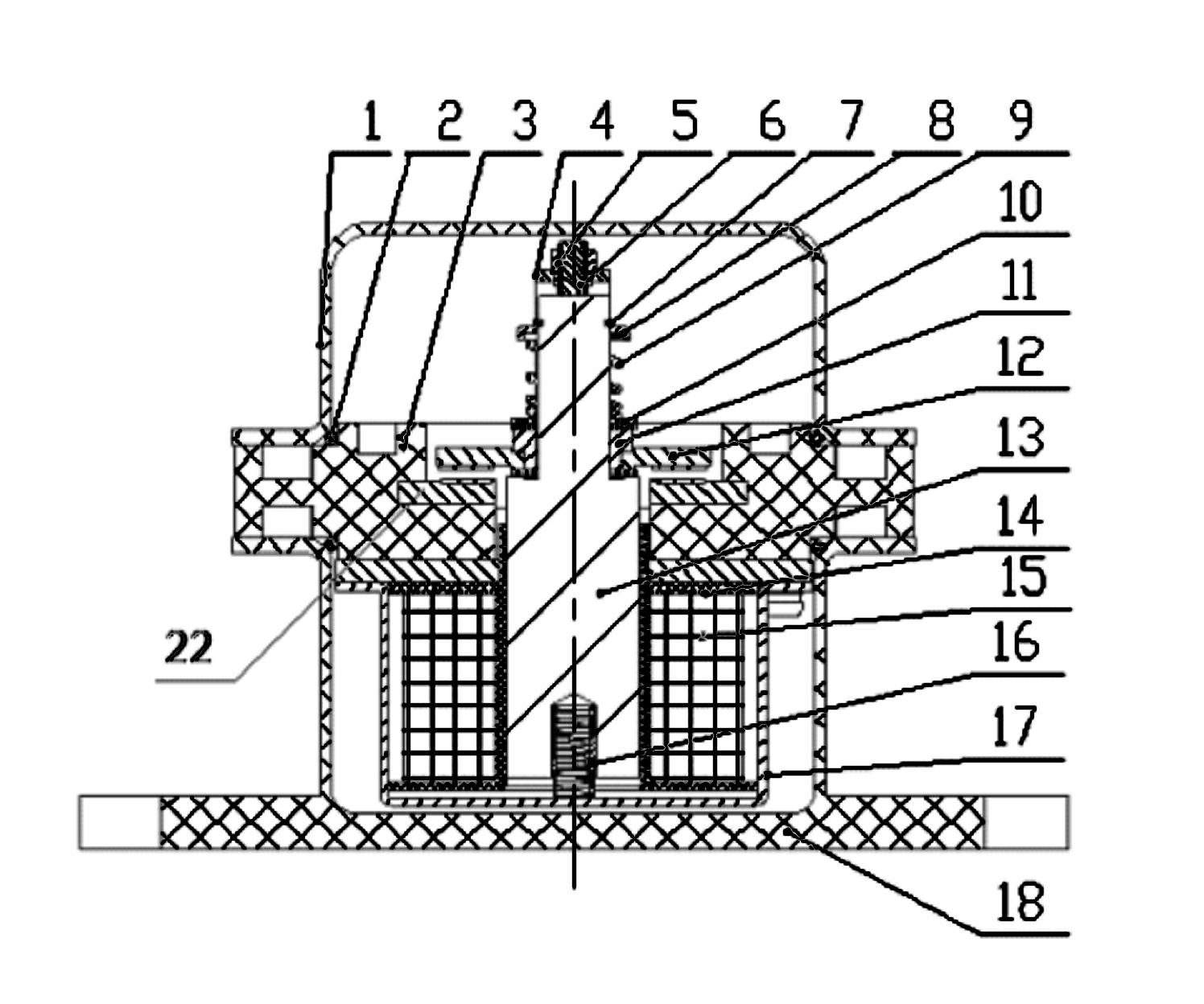
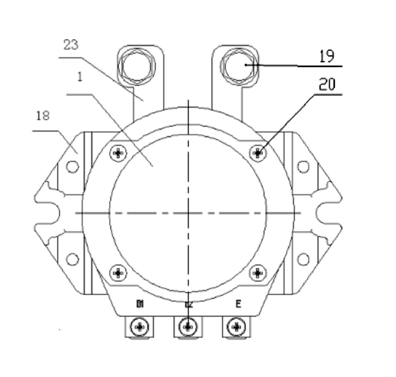
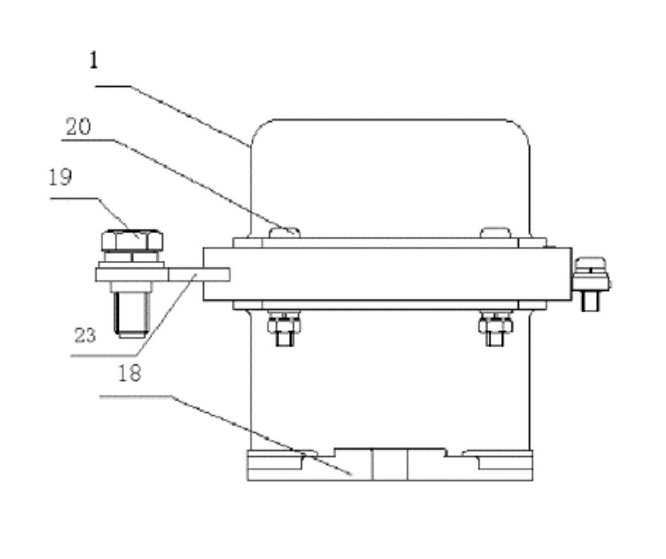
[0033] An adjustable electromagnetic power switch, such as figure 1 As shown, it includes an upper shell 1, a lower shell 18, a sealing ring 2, a bakelite bracket 3, a moving contact assembly 12, and a static contact assembly 22, and the bakelite bracket 3 is arranged between the upper shell 1 and the lower shell 18. , the sealing ring 2 is arranged between the upper shell 1 and the bakelite support 3, the center of the bakelite support 3 is provided with an iron core 13, the periphery of the iron core 13 and the lower part of the bakelite support 3 are provided with a coil frame assembly 14 and an enameled wire 15, and also includes a magnetically conductive The inner casing 17 encloses the iron core 13 , the bo...


PUM


Abstract

The invention relates to the technical field of automobile power supply switches, disclosing an adjustable electromagnetic power supply switch. The adjustable electromagnetic power supply switch comprises an upper casing (1), a lower casing (18), an iron core (13), a movable contact spring assembly (12), a static contact spring assembly (22), a coil rack assembly (14), an enamelled wire (15) and the like, wherein magnetic conduction inner casings (17) are additionally arranged on the outer sides of the iron core (13), the coil rack assembly (14) and the enamelled wire (15); the inside diameters of the magnetic conduction inner casings (17) are the same as the excircle diameter of the coil rack assembly (14); the upper casing (1) and the lower casing (18) are made of plastic; main contacts are respectively made of composite silver material; and adjusting screws (6) are additionally arranged at the top of the iron core. According to the adjustable electromagnetic power supply switch disclosed by the invention, the problem of overlow or overhigh pull-in voltage is solved; and the phenomenon that the switch is burnt down due to short circuit caused by contact of a spanner and the upper casing when the switch is replaced, can be also avoided. The adjustable electromagnetic power supply switch disclosed by the invention has the advantages of adjustable stroke, controllable clearance, cost saving, convenience for operation, safety and reliability.

Description

technical field [0001] The invention relates to an electromagnetic power switch device, in particular to an adjustable electromagnetic power switch suitable for automobile power supply. Background technique [0002] A general electromagnetic power switch includes a stationary part and a movable part, wherein the stationary part mainly includes a coil, a magnetic plate and a coil frame, and the movable part mainly includes an armature and a contact linked with the armature, and the armature is arranged in the coil frame of the static part , a coil is arranged on the periphery of the coil frame, and one end of the coil frame is connected with a magnetically conductive plate. When the coil is powered or powered off, the magnetic field generated by the coil acts on the armature in the middle of the coil frame, causing the armature to make a linear telescopic movement, thereby driving the opening and closing of the contacts connected to the armature to complete the switching func...

Claims


Application Information

Patent Timeline
Patent Type & Authority Applications(China)
IPC IPC(8): H01H50/04
Inventor 吴升学尚学虹
Owner RUILI GROUP RUIAN AUTO PARTS CO LTD
Why Eureka
Try Eureka