Supercharge Your Innovation With Domain-Expert AI Agents!

Method for balancing load of nodes in grid wireless sensor network (WSN) by minimum mean square error (MMSE) algorithm

A minimum mean square error and sensor network technology, applied in wireless communication, network topology, network traffic/resource management, etc., can solve problems such as energy imbalance and communication bottlenecks, and achieve the effect of solving the difference in energy consumption

Inactive Publication Date: 2013-11-06
HARBIN INST OF TECH
View PDF5 Cites 0 Cited by
  • Summary
  • Abstract
  • Description
  • Claims
  • Application Information

AI Technical Summary

Problems solved by technology

[0005] In order to solve the problem that the nodes on the selected route need to undertake a large number of packet relay work, resulting in energy imbalance and forming a communication bottleneck

Method used


Image

  • Method for balancing load of nodes in grid wireless sensor network (WSN) by minimum mean square error (MMSE) algorithm
  • Method for balancing load of nodes in grid wireless sensor network (WSN) by minimum mean square error (MMSE) algorithm
  • Method for balancing load of nodes in grid wireless sensor network (WSN) by minimum mean square error (MMSE) algorithm

Examples


specific Embodiment approach 1

[0015] The specific embodiment one, the method for utilizing the minimum mean square error algorithm to balance the load of each node in the wireless grid sensor network, it includes the following steps:

[0016] Step 1. Let there be m grids in the horizontal direction and n grids in the vertical direction in the rectangular interval from the source node to the central node;

[0017] Then there are (m+1)*(n+1) nodes in total. According to the shortest path algorithm, the shortest route length between the source node and the central node is m+n, and there are different routes, so construct a (m+1)*(n+1)-2 line, Column matrix A, where each column of matrix A represents a route, and each row represents whether a certain node appears in the route, all routes must pass through source nodes and destination nodes, so the number of nodes in the grid network can be Reduced to (m+1)*(n+1)-2,

[0018] Step 2, judging whether m+n is greater than 5, judging whether to execute step 3, j...

specific Embodiment approach 2

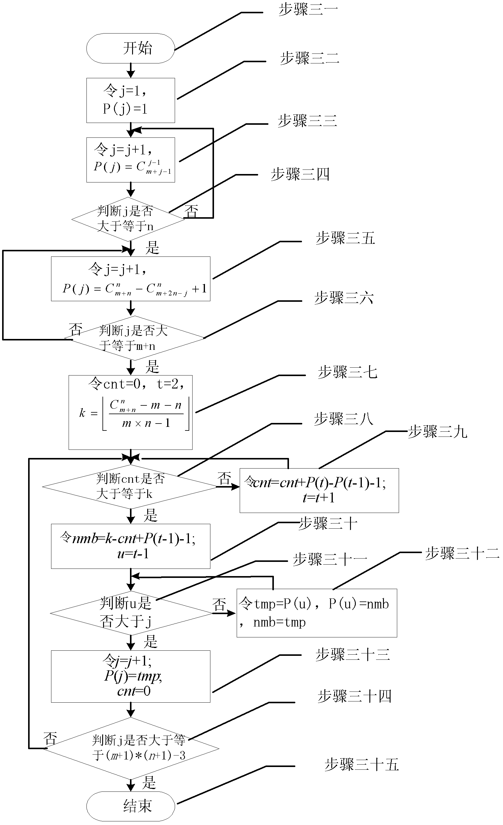
[0032] Embodiment 2. The difference between this embodiment and Embodiment 1 is that the latitude and longitude path selection algorithm in step 3 is:

[0033] Step 31, start, execute step 32;

[0034] Step 32, set j=1, P(j)=1, execute step 33;

[0035] Among them, j is the number of selected paths, P(j) is the index number of the jth path in the full path in descending order, and the i-th row and the sth column element in the full-path matrix represent the i-th path’s Whether the s jump is in the horizontal direction, if the value of the element is 1, it means along the horizontal direction; otherwise, if the value of the element is 0, then it means along the vertical direction, if each row in the matrix is ​​regarded as a set of binary numbers, and These rows are arranged in descending order from top to bottom in order from large to small, then each raster map can uniquely correspond to a full path matrix, which has a total of Row, that is, the combination number of n num...

specific Embodiment approach 3

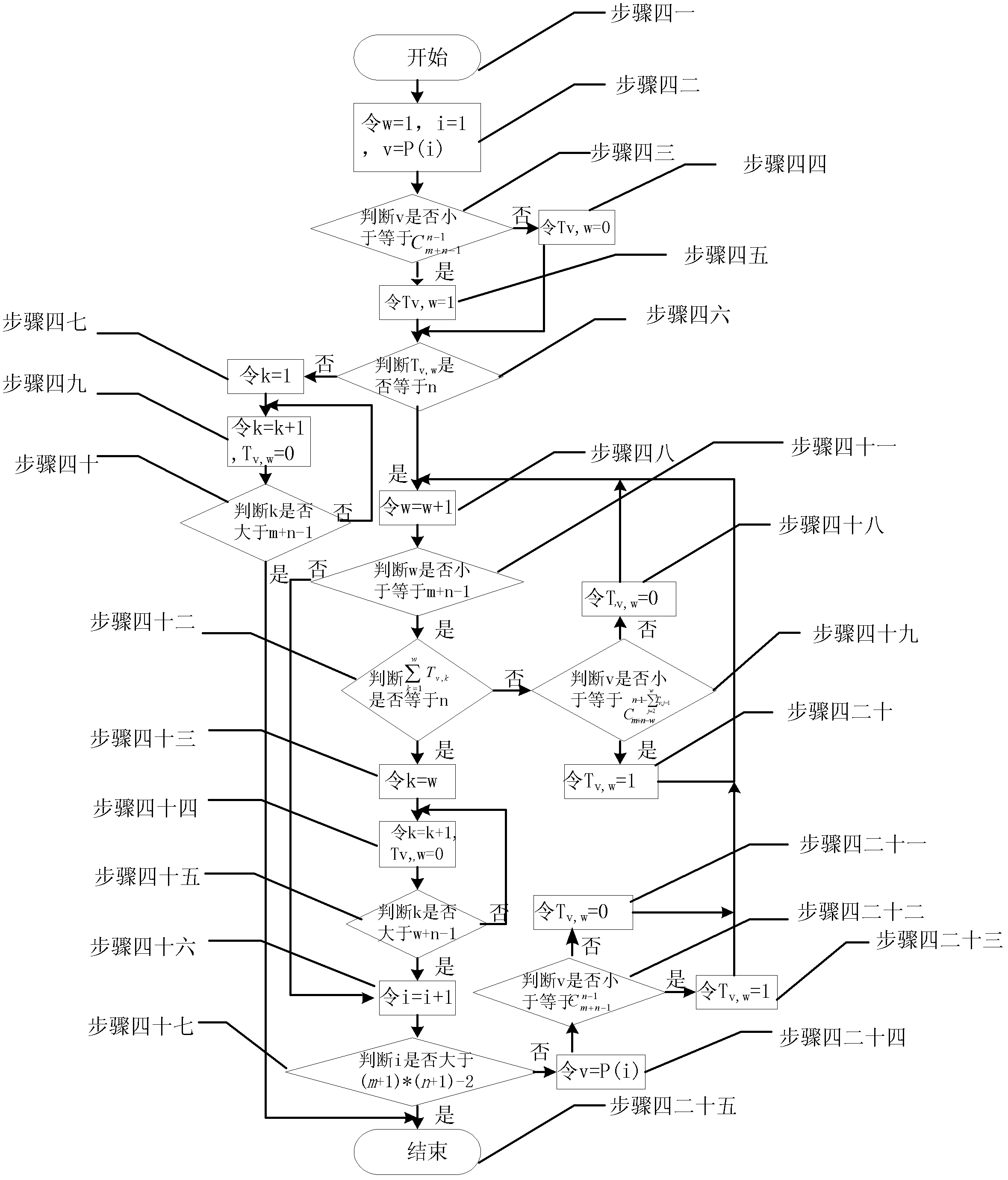
[0057] Specific embodiment three, the difference between this embodiment and specific embodiment one is: the transition matrix T construction algorithm in step 4 is:

[0058] Transition matrix T construction algorithm:

[0059] Step 41, start, execute step 42;

[0060] Step 42, let w=1, i=1, v=P(i), execute step 43;

[0061] Among them, w is the number of hops of the path, i is the i-th longitude-latitude path, v is the number of paths, P(i) is the index value of the selected i-th longitude-latitude path in the whole path,

[0062] Step 43: Determine whether v is less than or equal to If the judgment result is yes, execute steps 4 and 5; if the judgment result is no, execute steps 4 and 4;

[0063] Step 44, make T v,w =0, execute steps four and six;

[0064] Among them, T v,w is the element in row v and column w in the transition matrix T, T v,w =0 is to assign 0 to the element in row v and column w in the transfer matrix T,

[0065] Step four and five, make T v,w =1...


PUM


Abstract

The invention relates to a method for balancing load of nodes in a grid wireless sensor network (WSN) by a minimum mean square error (MMSE) algorithm, and is used for solving the problem that nodes on a selected route need to undertake a large quantity of packet trunking work to cause unbalanced energy. The method comprises the following steps: selecting an alternative route from all the alternative routes according to a longitude and latitude algorithm; determining the selected ratio of the alternative routes according to the MMSE method; and then using the alternative routes based on the ratio by source nodes so as to realize optimum node load balance. The method is applicable to the WSN.

Description

technical field [0001] The invention relates to a wireless sensor network routing technology, in particular to a method for balancing the load of each node in the wireless grid sensor network by using the minimum mean square error algorithm. Background technique [0002] Nodes in wireless sensor networks are usually battery powered and have limited processing power. Therefore, wireless sensor networks usually adopt multi-hop relay communication, and achieve the purpose of saving power consumption and increasing processing capacity through distributed cooperation. In practical applications, the data monitored by wireless sensors usually needs to be associated with their geographic location information, so as to provide a basis for the decision-making of the central node to form a network situation. However, due to the limitation of size, energy consumption and processing power, it is too expensive to use positioning technologies such as GPS or distributed position estimation...

Claims


Application Information

Patent Timeline
Patent Type & Authority Patents(China)
IPC IPC(8): H04W28/08H04W40/00H04W84/18
Inventor 吴少川白旭高玉龙张佳岩张文彬管修挚王思
Owner HARBIN INST OF TECH
Features
  • R&D
  • Intellectual Property
  • Life Sciences
  • Materials
  • Tech Scout
  • Unparalleled Data Quality
  • Higher Quality Content
  • 60% Fewer Hallucinations
Learn More