Laminated filter unit

A technology of lamination filtration and lamination group, which is applied in the direction of filtration separation, filtration circuit, fixed filter element filter, etc. It can solve the problems of poor cleaning effect, ineffective cleaning of impurities, and difficulty in installation and maintenance.

Inactive Publication Date: 2012-05-02
乌鲁木齐瑞拓环保设备制造有限公司
View PDF4 Cites 9 Cited by
  • Summary
  • Abstract
  • Description
  • Claims
  • Application Information

AI Technical Summary

Problems solved by technology

[0002] In order to ensure that the filter group can work normally, safely and effectively when the traditional filter unit is composed of a filter group, a centrifugal sand separator device must be added to the front of the equipment to reduce the workload of the filter group. The disadvantages of configuration are: high investment cost, large occupied area, and difficult installation and maintenance
The structure of the traditional laminated filter stack is tightly connected under any circumstance

Method used


Image

  • Laminated filter unit
  • Laminated filter unit
  • Laminated filter unit

Examples


Embodiment Construction

[0020] The preferred embodiments of the present invention will be described below in conjunction with the accompanying drawings. It should be understood that the preferred embodiments described here are only used to illustrate and explain the present invention, and are not intended to limit the present invention.

[0021] Such as Figure 1-Figure 6 Shown:

[0022] filter:

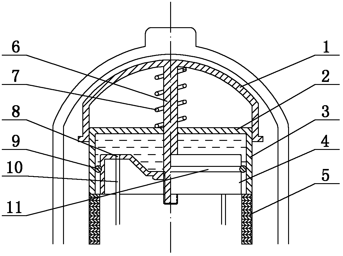
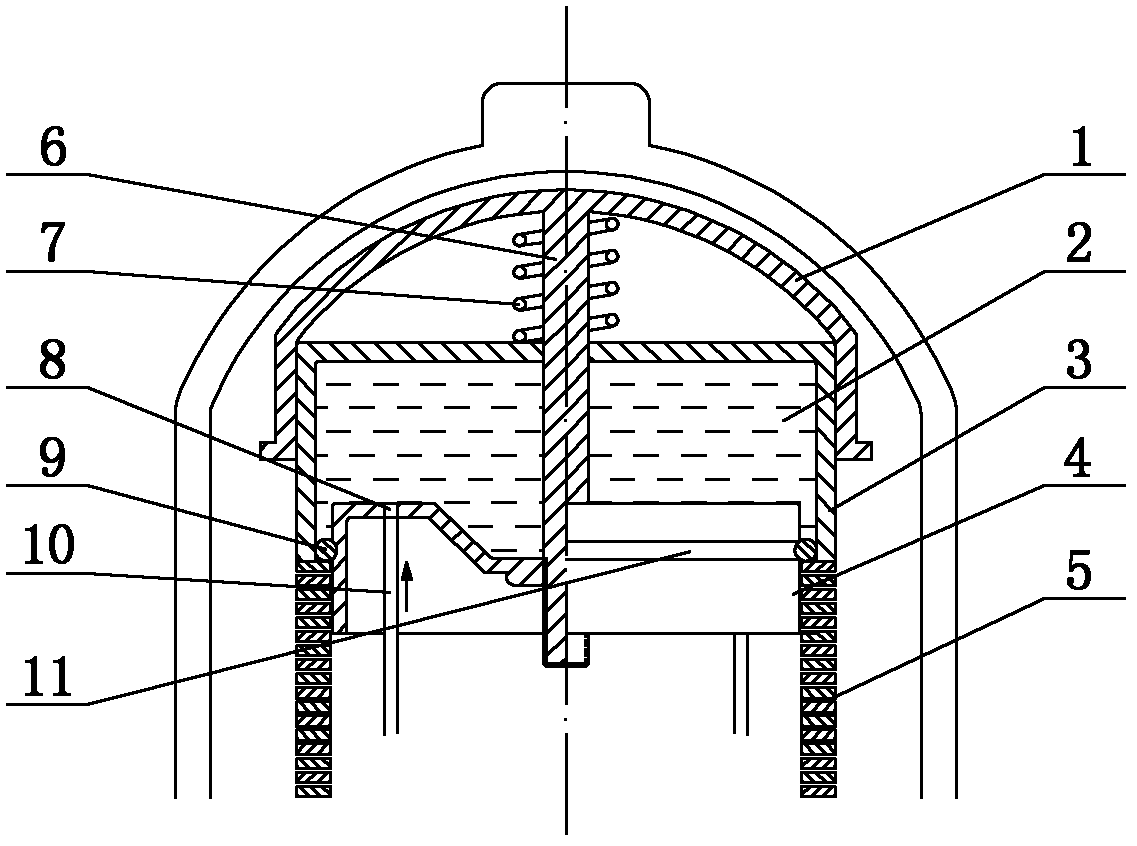
[0023] The liquid containing impurities enters the interior of the laminated filter unit from the inlet and enters the centrifugal guide vanes 12. When the liquid passes through the centrifugal guide vanes 12, high-speed rotation occurs, and the centrifugal force generated by the high-speed rotating liquid keeps the impurities in the liquid away from the laminated stack 5 And move up, and finally concentrate on the top of the laminated filter unit, which greatly reduces the backwashing frequency of the product. Under the action of the system pressure, the liquid is filtered through the gap of the laminati...


PUM


Abstract

The invention relates to a laminated filter unit, which belongs to a component of a laminated filter. The filter unit comprises a shell, wherein the shell is provided with an inlet and an outlet; a piston, a piston sleeve and a piston seat are arranged in the shell; the side wall of the piston sleeve is arranged on a lamination assembly; the lower part of the lamination assembly is provided with centrifugal flow guide blades; and a check valve is arranged between the centrifugal flow guide blades and the outlet. Impurities in liquid get away from the lamination assembly and move upwards by centrifugal force produced by the liquid rotating at a high speed and are finally centralized at the top end of the laminated filter unit, so that the back wash frequency of a product is greatly reduced. In a back wash state, after a high-pressure clean water flow is gathered to a flow guide pipe in a reverse direction, the water flow enters a piston chamber through a piston hole at the top end of the flow guide pipe, and the piston sleeve overcomes outward movement of the spring pressure on the top so as to release the pressure applied to the lamination assembly; and by now, the lamination assembly is loose, and the cleaning water flow can extremely easily pass through each lamination to clean impurities inside and outside a laminated filter tank.

Description

technical field [0001] The invention relates to a laminated filter unit, which belongs to the components of the laminated filter. Laminated filters are widely used in water filtration in food, textile, metallurgy, plastics, medicine, papermaking and construction industries. The filtration level is determined according to the water quality requirements of the subsequent water system or equipment, and the water quality requirements of the water use occasions. Background technique [0002] In order to ensure that the filter group can work normally, safely and effectively when the traditional filter unit is composed of a filter group, a centrifugal sand separator device must be added to the front of the equipment to reduce the workload of the filter group. The disadvantages of the configuration are: high investment cost, large occupied area, and difficult installation and maintenance. The structure of the traditional laminated filter stack is tightly connected in any case. In ...

Claims


Application Information

Patent Timeline
IPC IPC(8): B01D36/00B01D29/46B01D29/68
Inventor 黄文军游爱民
Owner 乌鲁木齐瑞拓环保设备制造有限公司
Why Eureka
Try Eureka