A Three Dimensional Printing Apparatus, a Material Dispensing Unit Therefor and a Method

a three-dimensional printing and material technology, applied in the direction of additive manufacturing processes, manufacturing tools, applying layer means, etc., can solve the problems of difficult inability to accurately print, and inability to have more than one material per layer, etc., to achieve convenient interchangeability, increase the degree of detail and accuracy, and improve the effect of quality

Inactive Publication Date: 2018-12-20
BURT MAXIMILIAN BARCLAY
View PDF6 Cites 4 Cited by
  • Summary
  • Abstract
  • Description
  • Claims
  • Application Information

AI Technical Summary

Benefits of technology

[0069]The particle size quoted for a supply of the particulate material, such as powder, usually refers to the maximum particle diameter. For example, a batch of 100 micron (0.1 mm) powder will contain any particles under 100 microns (0.1 mm) in diameter but none greater than 100 microns (0.1 mm). Commonly used powders in Selective Laser Sintering that are suitable for use with the present invention are 100 micron (0.1 mm) powders, 200 micron (0.2 mm) powders, 50 micron (0.05 mm) powders and 20 micron (0.02 mm) powders. These sizes are usually dictated by the preferred layer thickness of any object being built. The process by which powders of certain sizes are made may not be not entirely perfect therefore occasionally some particle sizes will be greater than the quoted maximum diameter and it is within reason that a negligible portion of a volume of 100 micron (0.1 mm) powder may in fact be 250 microns (0.25 mm). It is up to the quality control of supplier to determine the accuracy of the quoted size. Therefore many suppliers state the quality of their powders using a percentage, for example, a batch of 100 micron (0.1 mm) powder guarantees that at least 90% of the volume of powder is below 100 microns (0.1 mm) in diameter. Some suppliers even state the minimum powder diameters as a percentage as well, such as in a batch of 100 micron (0.1 mm) powders, no more than 2% of the powder will be smaller than 30 microns (0.03 mm) in diameter. However, it is the maximum diameter specified on the batch that is used when adjusting the size of the nozzle of the 3D printer of the present invention.
[0070]In the present invention, particles of a range of diameters will actually contribute to the material density of the finished article, as smaller particles of powder will fill any gaps that exist when closely packing similar size particles, but the different diameters will all be equal or less than the specified maximum particle diameter. The size of the through passage of the nozzle of the 3D printer of the invention will ensure that a volume of particulate material no greater than the largest particle diameter (such as, for example, 100 microns or 0.1 mm) is allowed to pass through the nozzle. This may mean a single particle with 100 micron (0.1 mm) diameter or the equivalent volume of smaller powders such as 4 particles with 50 micron (0.05 mm) diameter. The end result will still be that the deposited layer of particulate material will be of uniform thickness (such as, for example, 100 microns or 0.1 mm thick).
[0071]Different versions of powder dispensing units may be made bespoke for different maximum sizes of particulate material, such as 500 microns (0.5 mm) for faster building or 20 microns (0.02 mm) for greater detail and accuracy. These different dispensing units are preferably easily interchangeable within the 3D printer of the invention, allowing a user to select particle sizes and layer thicknesses depending on the desired speed or detail of their printing.
[0072]The nozzle of the dispensing unit should not get clogged if an odd oversized particle tries to enter it. Due to its greater diameter the particle will be unable to fit into the through passage of the nozzle. Since no force other than gravity pushes it down, when the valve of the dispensing unit closes again the oversized particle will simply be pushed away from the entrance to the through passage. However, while the through passage remains open, the oversized particle will prevent smaller particles from entering the through passage and this may affect the quality of the finished article. To address this issue, each layer can be scanned to detect gaps in the deposited material and the 3D printer of the invention can be allowed to pass over the empty region and fill it.
[0073]A filter can be provided in the delivery arrangement or in the storage vessel to filter out oversized particles prior to dispensing the particulate material into the through passage of the nozzle. For example, a sheet filter (for example, a sheet of thin metal uniformly sized holes) may be positioned in the delivery arrangement or in the storage vessel. Any oversized particles will be unable to pass through the filter and remain above the filter to be brushed off. This ensures only particles of diameter equal or less the maximum specified diameter can enter the dispensing units. However, filters are also not perfect, quality affects their performance and many filters use the same specifications as powder when quoting performance, such as for example a guarantee to remove 95% of particles greater than the maximum specified diameter. Other filters use what is called an Absolute Micron Rating, which can guarantee filtering accuracy to 99%. For these reasons, in the present invention, the through passage itself may be considered as a filter.
[0074]As particulate material is reused and recycled in the 3D printer, its particles can eventually lose its roundness, sometimes they can flatten, due to thermal and / or mechanical stress, which render them no longer fit for use. In this case a filter can prove useful as a means of ensuring that recycled powder is not contaminated by damaged powder. Alternatively, a limited number of times, such as for example, ten times, of reusing the powder can be specified and adhered to.

Problems solved by technology

Disadvantages of the SLS method include the ability only to form a whole layer of the same material, the need for a roller to even out the laid powder and as a result, inaccuracies in the finished article.
Disadvantages of the FDM method lie in that it is difficult to have more than one material per layer and that support structure has to be created separately using a second filament and subsequently removed from the finished article.
A further disadvantage is that when the drops of melted plastic are dragged across the build plate a clean drag is unlikely to be obtained and therefore accuracy of the finished article is likely to be compromised.
A further disadvantage of this method is that it can only use light curable resins and cannot use other materials, for example, metals or ceramics.
This makes the process of creating a 3D object time consuming.

Method used


Image

  • A Three Dimensional Printing Apparatus, a Material Dispensing Unit Therefor and a Method
  • A Three Dimensional Printing Apparatus, a Material Dispensing Unit Therefor and a Method
  • A Three Dimensional Printing Apparatus, a Material Dispensing Unit Therefor and a Method

Examples


Embodiment Construction

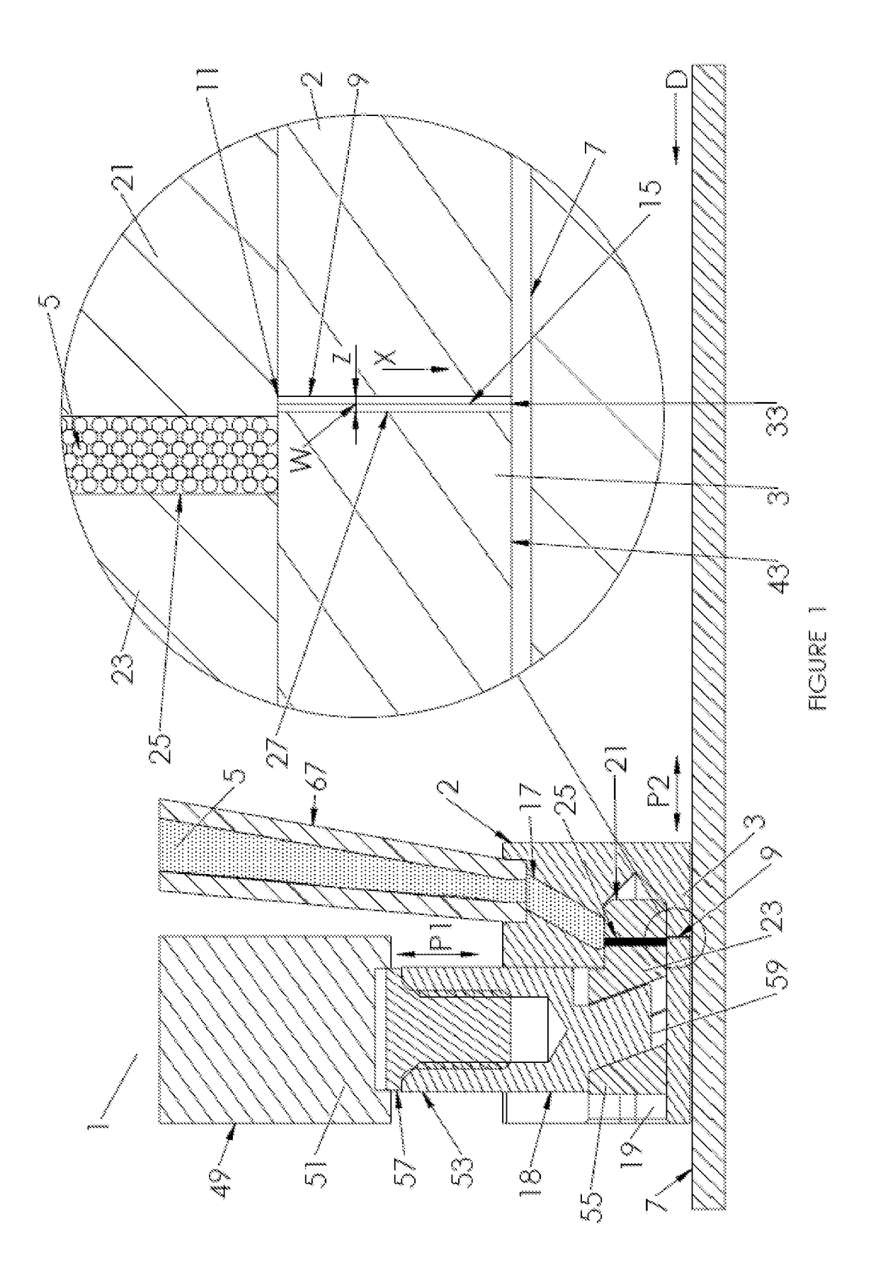
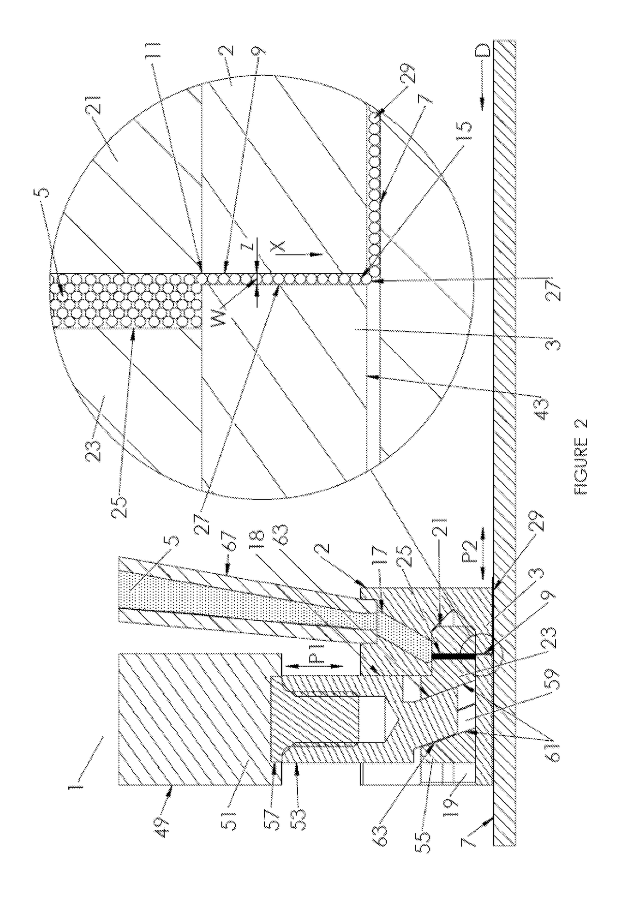
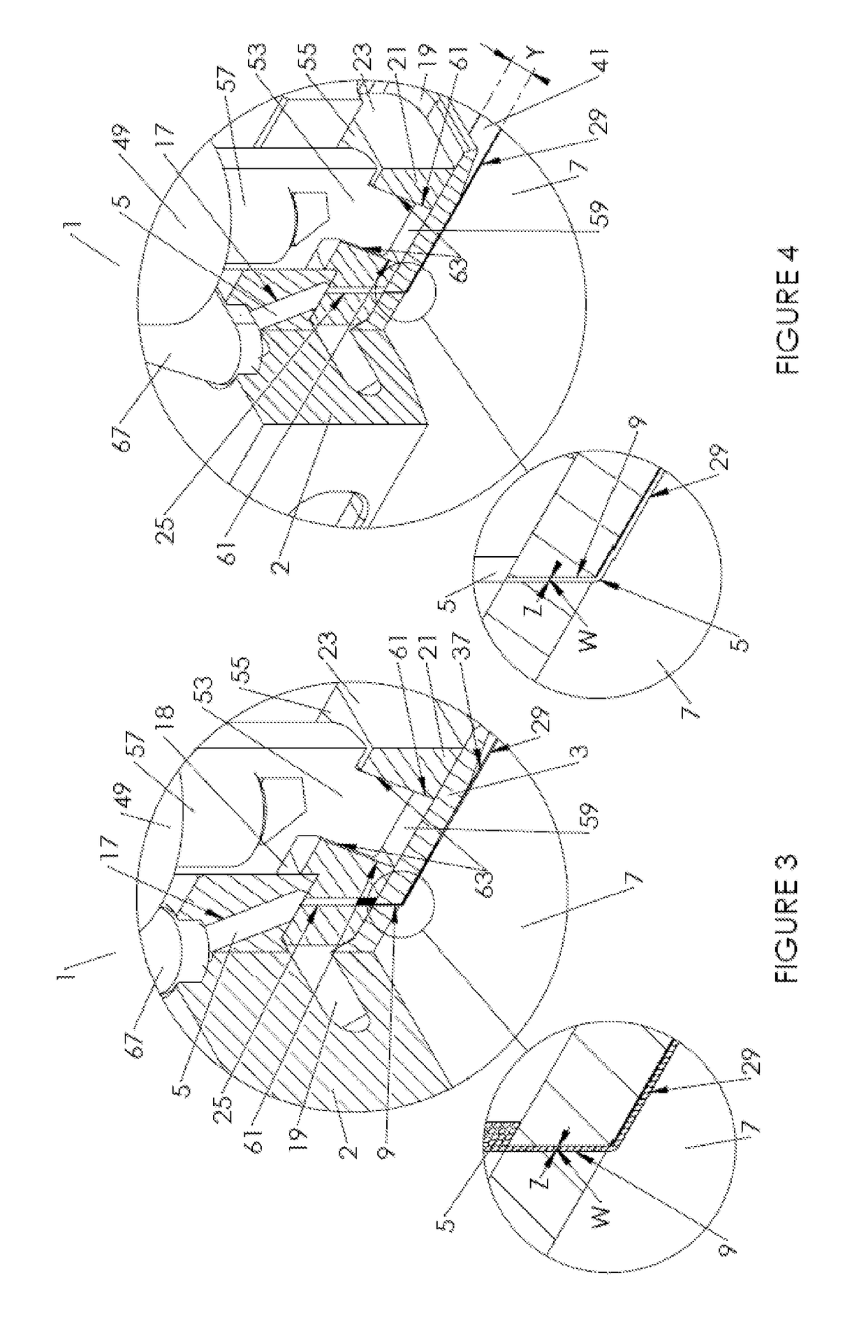
[0120]Referring to FIGS. 1 to 25, a three dimensional (3D) printing apparatus for forming three dimensional objects, a material dispensing unit therefor and a corresponding method of three dimensional printing will now be jointly described. The material dispensing unit of the invention is indicated generally using reference numerals 1 and 10 in the Figures. The 3D printing apparatus of the invention is indicated generally by reference numerals 100 and 200 in the Figures.

[0121]Referring initially to FIGS. 1 to 4, the material dispensing unit 1 for the three dimensional printing apparatus 100 comprises a housing 2 incorporating a nozzle 3 for depositing particulate material 5 on a build surface 7. It will be appreciated that in the present specification, for brevity, the term “build surface”, unless otherwise specified, includes an upper surface of a newly created layer onto which a subsequent layer is to be deposited as well as an upper surface of a build plate (to be described below...


PUM

PropertyMeasurementUnit
rotationaaaaaaaaaa
diameteraaaaaaaaaa
diameteraaaaaaaaaa

Abstract

A material dispensing unit (1; 10) for a three dimensional printing apparatus (100; 200) has a nozzle (3) for depositing particulate material (5; 220a, 220b; 224; 226) on a build surface (7), where the nozzle defines a through passage (9) for the material. The through passage has an inlet end (11) for receiving the material and an outlet end (15) for dispensing the material. A valve (21) is provided at least one of at, within or in fluid communication with the through passage for controlling flow of the material via the through passage, the valve being operable between open and closed positions. Flow of said material into the through passage is blocked when in the closed position and, when in the open position, flow of the material into the through passage is allowed. A method of forming a three dimensional object (31) is also disclosed, as is a three dimensional printing apparatus (200) comprising one or more dispensing units (la; b) for dispensing particulate material (220a, 220b; 224; 226), an enclosure (137) for containing the material dispensed by the one or more dispensing units and one or more heating elements (210, 212) for heating the material contained in the enclosure to a first predetermined temperature.

Description

FIELD OF THE INVENTION[0001]The invention relates to a three dimensional (3D) printing apparatus (aka additive manufacturing apparatus) for forming three dimensional objects, a material dispensing unit therefor and a corresponding method of three dimensional printing.BACKGROUND OF THE INVENTION[0002]3D printing is a process of making three dimensional solid objects from a digital file under computer control. The creation of a 3D printed object is achieved using additive processes by laying down successive thin layers of material until the entire object is created. A variety of 3D printing solutions exist differing mainly in the way layers are built to create the final object. Some methods produce the layers by binding powdered or granular material, others use curing soft or melted material.[0003]Selective laser sintering (SLS) and fused deposition modelling (FDM) are the most common technologies using this way of printing.[0004]SLS uses a tank filled with powdered or granular materi...

Claims


Application Information

Patent Timeline
Patent Type & Authority Applications(United States)
IPC IPC(8): B29C64/209B29C64/153B29C64/393B33Y10/00B33Y30/00B33Y50/02
CPCB29C64/209B29C64/153B29C64/393B33Y10/00B33Y30/00B33Y50/02B29C31/02B33Y40/00B29C31/045Y02P10/25B22F12/38B22F10/28B22F12/13B22F12/53B33Y40/20B29C64/20B29C64/255B29C64/295B29C64/141B22F10/00
Inventor BURT, MAXIMILIAN BARCLAY
Owner BURT MAXIMILIAN BARCLAY
Why Eureka
Try Eureka