
Front-bag and rear-electricity combined flow distribution deduster

A technology of bag dust removal and electric dust removal, which is applied in the direction of combination device, separation method, and dispersed particle separation, etc., which can solve the problems of adverse effects of filter bag use, leakage or pipe burst, etc., and achieve low emission concentration, excellent performance, and stable dust removal effect Effect

Active Publication Date: 2012-05-02
科林环保技术有限责任公司
View PDF2 Cites 2 Cited by
  • Summary
  • Abstract
  • Description
  • Claims
  • Application Information

AI Technical Summary

Problems solved by technology

In order to avoid a sudden rise in the temperature of the flue gas in the dust removal system, or when the four tubes of the boiler gas saving, reheater, superheater, and water wall leak or burst, especially when the boiler is frequently shut down, the The soot generated during ignition and start-up will have a negative impact on the use of the filter bag. Therefore, a dust collector that can meet the requirements of the bag filter and has an electrostatic precipitator that can adapt to high temperature, high humidity, and oily smoke is used for It is very urgent technically and economically to solve the problems of the above-mentioned known dust collector structure.

Method used


Image

  • Front-bag and rear-electricity combined flow distribution deduster
  • Front-bag and rear-electricity combined flow distribution deduster
  • Front-bag and rear-electricity combined flow distribution deduster

Examples


Embodiment Construction

[0024] The present invention will be further described below in conjunction with accompanying drawing and embodiment:

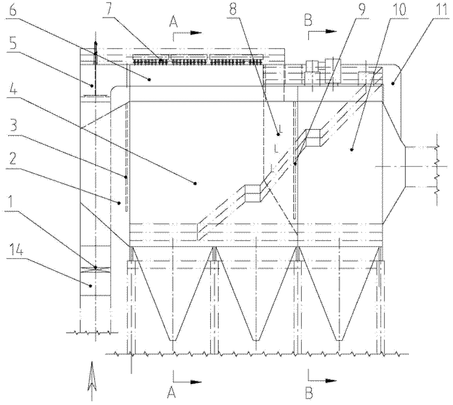
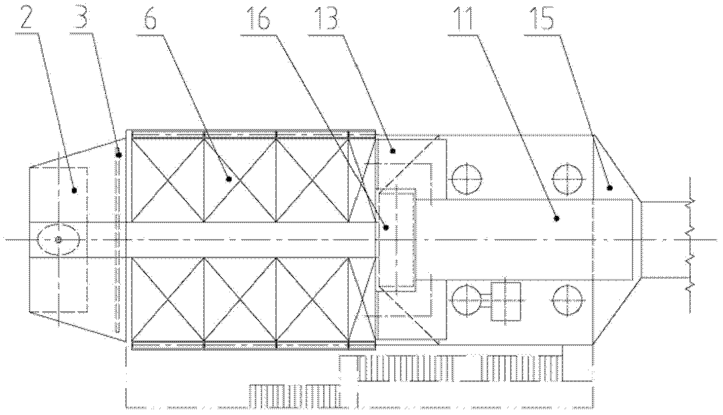
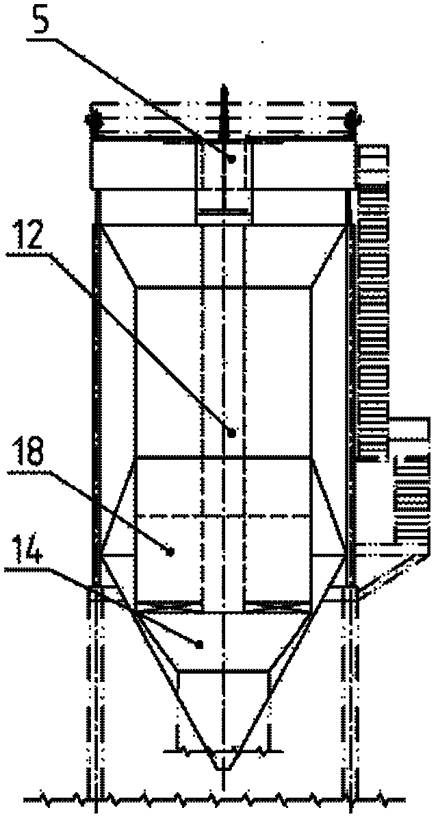
[0025] As shown in the figure, a combined shunt dust collector with front bag and rear electricity includes a dust removal box, an air inlet pipe and an air outlet pipe connected to the dust removal box, and an ash hopper connected to the lower part of the dust removal box. Specifically:

[0026] The dust removal box includes a bag dust removal box and an electric dust removal box 10, wherein the bag dust removal box includes a bag dust removal upper box 6 and a bag dust removal middle box 4, and the bag dust removal upper box 6 is provided with a bag dust removal cleaning spray Blowing device 7, bag dust removal filtering device 17 is arranged in box 4 in bag dust removal. A complete electrostatic precipitator is provided in the electrostatic precipitator box 10 .

[0027] The air inlet pipe includes: the bag dust removal air inlet pipe 18 connecte...


PUM


Abstract

The invention relates to a front-bag and rear-electricity combined flow distribution deduster, which comprises a dedusting box body, an air inlet pipe and an air outlet pipe which are communicated with the dedusting box body and an ash bucket connected to the lower part of the dedusting box body, wherein the dedusting box body comprises a bag dedusting box body and an electric dedusting box body; the air inlet pipe comprises a bag dedusting air inlet pipe communicated with the bag dedusting box body and an electric dedusting air inlet pipe which is communicated with the electric dedusting box body; the bag dedusting air inlet pipe is provided with a bag dedusting air inlet valve, and the electric dedusting air inlet pipe is provided with an electric dedusting air inlet valve; and the air outlet pipe is communicated with the bag dedusting box body and the electric dedusting box body. The front-bag and rear-electricity combined flow distribution duster integrates the advantages of an electric deduster and a bag type deduster, the electric deduster and the electric deduster run in a partition mode and are switched mutually, and the characteristics of the electric deduster and the bag type deduster are exerted to meet the requirements of working conditions that a boiler is frequently halted and started; and by the front-bag and rear-electricity combined flow distribution deduster, the damage of pipe explosion of the boiler to a filter bag is avoided effectively, the safety of the filter bag is ensured, bypass smoke gas can be purified effectively during the starting of fuel oil in the boiler, and the requirement of environmental protection is met.

Description

Technical field [0001] The present invention involves a combination of a front bag and a combination of diversion dust collectors. Background technique [0002] The dust collector's dust collector is based on the dust of dust in the high -voltage electric field, which is then arrested on the dust collection pole to achieve a gray gas separation.Due to the small particle size and light weight, the amount of electricity is low in weight, and the "second dust" caused by the ashes, it is difficult to collect it by the electric dust collector.It can be said that the dust collector's dust collector's dust removal mechanism limits its further improvement of the dust removal efficiency. The conventional electric dust collector must reach 30mg / nm 3 This new emission standard is very difficult or not economical. [0003] The bag dust collector is achieved through the mechanical filtering effect of the dust layer attached to the filter material to achieve the purpose of the dust.The fine ...

Claims


Application Information

Patent Timeline
IPC IPC(8): B01D50/00
Inventor 陈英明
Owner 科林环保技术有限责任公司
Learn More