Laying head using dynamic-static pressure oil film bearing

An oil film bearing, dynamic and static pressure technology, applied in the direction of sliding contact bearings, rotating bearings, bearings, etc., can solve problems that are not conducive to mechanical installation and maintenance disassembly, contact between rotor and oil film bearing, trivial design, etc., to achieve good precision Retention, strong load capacity, and large contact area

Inactive Publication Date: 2012-05-02
汉威广园(广州)机械设备有限公司
View PDF6 Cites 10 Cited by
  • Summary
  • Abstract
  • Description
  • Claims
  • Application Information

AI Technical Summary

Problems solved by technology

[0005] However, the hydraulic bearing mainly mentioned in this patent adopts a dynamic pressure bearing design, which is easy to cause contact between the rotor and the oil film bearing durin

Method used


Image

  • Laying head using dynamic-static pressure oil film bearing
  • Laying head using dynamic-static pressure oil film bearing
  • Laying head using dynamic-static pressure oil film bearing

Examples


Embodiment Construction

[0017] The specific embodiments of the present invention will be further described below in conjunction with the accompanying drawings.

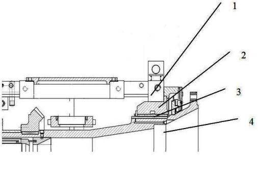
[0018] like figure 1 As shown, a laying machine using dynamic and static pressure oil film bearings, the rotor (4) is fixed on the support structure (1) through the dynamic and static pressure oil film bearing device (3) and the support bearing (2), and the rotor (4) is driven by external force Drive other parts of the spinning head of the spinning disc to work to complete the spinning process.

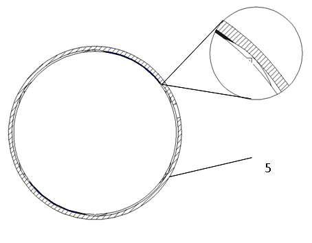
[0019] like figure 2 As shown, the oil film bearing (5) is an integral annular design, which is integrally formed in the process of processing, and has high rigidity and high load-carrying capacity. The hydrostatic oil film bearing device (3) is composed of an oil film bearing (5) and a cavity formed between the oil film bearing (5) and the rotor (4).

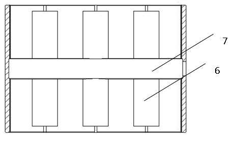
[0020] like image 3 As shown, six grooves (6) are evenly distributed on the inner side of t...


PUM


Abstract

The invention provides a laying head using a dynamic-static pressure oil film bearing. The laying head comprises a support structure, a support bearing, a dynamic-static pressure oil film bearing device and a rotor, wherein the rotor is fixed on the support structure through the dynamic-static pressure oil film bearing device and the support bearing, the dynamic-static pressure oil film bearing device adopts the oil film bearing with an all-round structure, a plurality of grooves are arranged on the surface on the inner side of the oil film bearing, an oil cavity with different depths is formed between the oil film bearing and the rotor, when a system works, the rotor floats up under the action of a layer of pressure oil film, the rotor is suspended between the bearings when a motor is not driven, and mechanical friction and abrasion are avoided, therefore the service life of each bearing is further prolonged and good precision retentivity is realized.

Description

technical field [0001] The invention relates to the field of high-speed wire production equipment, in particular to a laying machine using a dynamic and static pressure oil film bearing. Background technique [0002] In the high-speed wire production process, the laying machine is one of the core equipment, and its function is to turn the straight finished wire into a coil for transportation and use. The action part of the laying machine is mainly composed of a rotating body and a rotating tube, and the rotating tube is installed in the rotating body. The rotor is fixed to the stator housing of the gearbox by bearings. The rotor is driven by power and rotates around its axis at a speed of 2700 rpm or even higher. The designed linear speed of the wire in the laying machine can reach up to 112m / s, and the current maximum speed has reached 160m / s in the process of continuous technological upgrading. So now the speed of the spinning machine is getting higher and higher. [0...

Claims


Application Information

Patent Timeline
IPC IPC(8): B21B41/00F16C17/00F16C32/06
Inventor 成西平
Owner 汉威广园(广州)机械设备有限公司
Why Eureka
Try Eureka