
Method for combining amorphous alloy and heterogeneous material and complex

A technology of amorphous alloys and heterogeneous materials, applied in chemical instruments and methods, thin material processing, metal layered products, etc., can solve the problems of limiting amorphous alloy system, high cost, increasing production cost, etc., to reduce forming The requirements of capacity and performance, the requirements for reducing elastic deformation, and the effect of improving bonding strength

Active Publication Date: 2012-05-02
BYD CO LTD
View PDF14 Cites 67 Cited by
  • Summary
  • Abstract
  • Description
  • Claims
  • Application Information

AI Technical Summary

Problems solved by technology

[0006] However, due to some characteristics of the amorphous alloy itself, its application has been greatly affected.
For example, the hardness of amorphous alloy is high, when it is necessary to perform cutting, punching and drilling on amorphous alloy products, it will increase the difficulty of the process, significantly shorten the life of the tool, and thus increase the production cost
In addition, for products with extremely complex structures and a wall thickness of less than 0.3mm, it will also make it difficult to form amorphous alloy products, which will greatly increase production costs, or even fail to produce
At the same time, since the plastic deformation of amorphous alloys is carried out in the form of the formation and expansion of low-viscosity regions of shear bands, amorphous alloys usually exhibit extremely low plastic deformation to appear as brittle materials, which greatly limits the Applications in devices requiring higher safety, such as applications in products with special requirements for product drop performance and product impact performance
At the same time, it also greatly limits the use of various amorphous alloy systems, especially low amorphous forming ability and low-cost amorphous alloy materials.
In addition, at present, amorphous alloys are usually composed of precious metals, and the cost of materials is high. At the same time, not all structures require the excellent performance of amorphous alloys in product structure design. Therefore, how to realize the low-cost application of high-cost materials needs to be solved. big problem
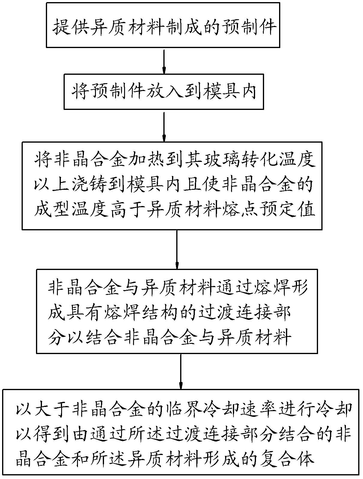
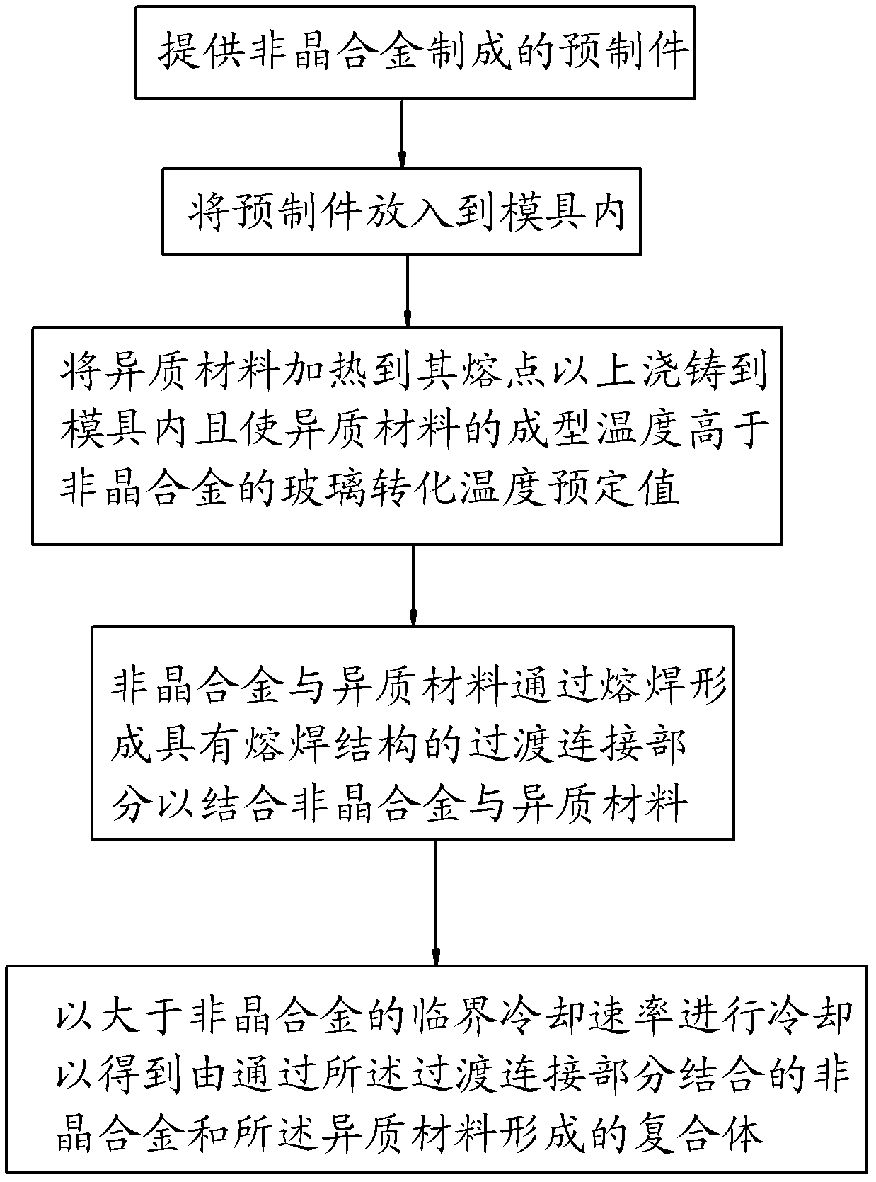
[0007] U.S. Patents US5482580, US6818078B2 and US6771490B2 disclose methods for compounding amorphous alloys and other materials. However, in the amorphous alloy composite products prepared by these conventional composite methods, the bonding strength between the amorphous alloy material and other materials is low. The impact resistance is low, and the method disclosed in the above-mentioned U.S. patent requires the melting point of the preform to be higher than the melting point of the material compounded with it, or requires the elastic limit of the amorphous alloy to be greater than 1.5% of the elastic limit value, thereby greatly limiting the amorphous alloy. The use of alloys and other materials to connect and compound
[0008] At the same time, in terms of connection technology, traditional technologies such as buckle, nut, welding, and bonding are widely used, but either due to low strength and poor reliability, or due to complicated procedures and high costs, even insert molding technology is also difficult due to differences in different materials. There is a problem of poor connection strength due to huge differences

Method used


Image

  • Method for combining amorphous alloy and heterogeneous material and complex
  • Method for combining amorphous alloy and heterogeneous material and complex
  • Method for combining amorphous alloy and heterogeneous material and complex

Examples


example 1

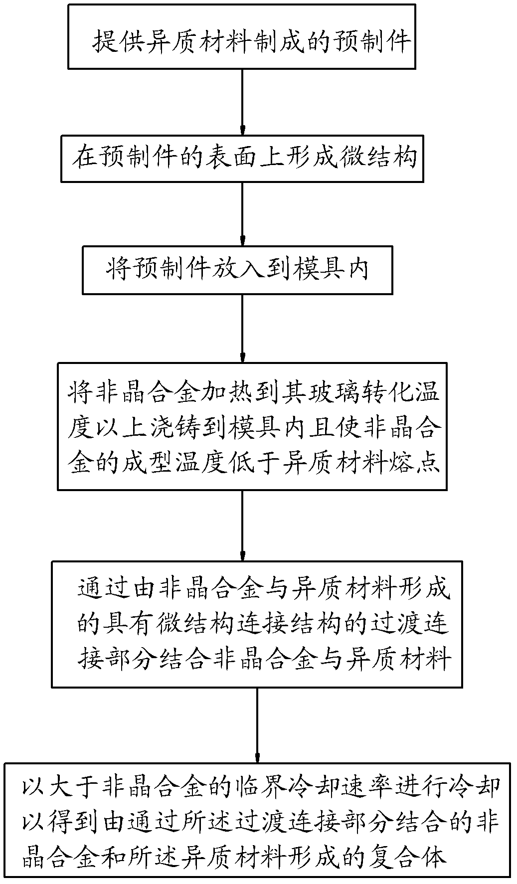
[0106] The glass transition temperature and melting point of the amorphous alloy obtained by the DSC curve test are 420 ° C and 835 ° C respectively, and are obtained by X Ray diffraction proves that the amorphous alloy is a complete amorphous structure; stainless steel, magnesium alloy, aluminum alloy, zinc alloy and amorphous alloy are respectively made Figure 12 Middle prefabricated part 12, its material is shown in Table 1, the prefabricated part cross-sectional size is 1.1mm×4.1mm, the length is 80mm, and the workpiece of 2mm×6mm×100mm is respectively prepared with stainless steel and amorphous alloy as a comparative example, in which stainless steel , magnesium alloy, and aluminum alloy are prepared by shot blasting to prepare the surface microstructure. After the preparation, the surface Ra is 100 μm, and then the stainless steel, magnesium alloy, aluminum alloy, and zinc alloy prefabricated parts are respectively placed in the die-casting mold and fixed. The amorphous...

example 2

[0111] The glass transition temperature and melting point of the amorphous alloy obtained by the DSC curve test are 420 ° C and 835 ° C respectively, and the X-ray Diffraction proves that the amorphous alloy is a complete amorphous structure; stainless steel, magnesium alloy, aluminum alloy, zinc alloy and amorphous are respectively made Figure 12 In the prefabricated part 12, the material of the heterogeneous material is shown in Table 2. The cross-sectional size of the prefabricated part is 1.1 mm × 4.1 mm, and the length is 80 mm. At the same time, a workpiece of 2 mm × 6 mm × 100 mm is prepared from an amorphous alloy as a comparative example. Among them, stainless steel, Magnesium alloys, aluminum alloys, and amorphous alloys are shot peened with steel shots of different particle sizes to obtain surface microstructures. The obtained surface microstructures are shown in Table 2, and then stainless steel, magnesium alloys, aluminum alloys, and zinc alloys are prefabricated ...

example 3

[0119] Table 3 below lists the performance comparison data of amorphous alloys and heterogeneous metal materials connected by fusion welding and non-fusion welding, in which the composition, melting point, glass transition temperature, melt forming temperature, and surface of the preform of the amorphous alloy The state, the melting point of the heterogeneous metal material, the molding temperature and the resulting connection method are listed in Table 3, and the connection performance data of the composite formed by the connection of the two heterogeneous materials are also listed in Table 3. The preparation method of composite molding of amorphous alloy and heterogeneous metal material is the same as Example 1.

[0120] It can be seen from Table 3 that the bonding strength and impact toughness of the amorphous alloy and the heterogeneous material according to the embodiment of the present invention are significantly higher than those of the comparative example, where part of...


PUM

PropertyMeasurementUnit
Critical dimensionaaaaaaaaaa
Sizeaaaaaaaaaa
Sizeaaaaaaaaaa

Abstract

The invention discloses a method for combining an amorphous alloy and a heterogeneous material and a complex formed thereby. The method comprises the following steps of: putting a prefabricated part made from one of the heterogeneous material and the amorphous alloy into a mould; heating the other one of the heterogeneous material and the amorphous alloy to a predetermined temperature and casting into the mould to form a transitional connection part combining the heterogeneous material and the amorphous alloy, wherein the transitional connection part has a fusion welding structure, a micro structural reinforcing connection structure or a mixed connection structure; and cooling at a speed greater than the critical cooling rate of the amorphous alloy to obtain the complex formed by the amorphous alloy and heterogeneous material. According to the method disclosed by the invention, the combination strength of the amorphous alloy and the heterogeneous material is enhanced, requirements on the forming capability and performance of the amorphous alloy are reduced, requirements on the elastic deformation of the amorphous alloy are reduced, and the applicability of the amorphous alloy is improved.

Description

technical field [0001] The invention relates to the field of amorphous technology, in particular to a method for combining amorphous alloys and heterogeneous materials and a composite body formed of amorphous alloys and heterogeneous materials. Background technique [0002] At present, there is an increasing demand for precise, durable, high-reliability, and high-strength product structures, but existing materials, molding technologies, and connection technologies are difficult to meet the design requirements of product structures. For example, although magnesium alloy materials are light in weight and can be precisely formed, they are poor in strength, easy to crack, and are not corrosion-resistant; although aluminum alloy materials can be precisely formed, corrosion-resistant and have colorful decorative properties, they have low hardness and are not wear-resistant; Although zinc alloy materials are cheap and easy to form, they have low strength and are not corrosion-resis...

Claims


Application Information

Patent Timeline
IPC IPC(8): B22D19/16B32B15/00B32B7/04
CPCB22D19/04B22D19/08B32B7/04B32B15/00B32B15/01B22D19/16C22C45/00C22C45/001C22C45/008C22C45/04C22C45/10Y10T428/12493B22D19/0081B22D17/00B22D21/00B22D21/005B22D21/007C22C9/02C22C9/08C22C18/04C22C21/08C22C23/02C22C38/001C22C38/002C22C38/02C22C38/04C22C38/54C22C45/02
Inventor 宫清张法亮李运春
Owner BYD CO LTD
Learn More