
Self-adaptive compensation method for detecting turning error of large part of rotary body

A technology of self-adaptive compensation and machining error, applied in turning equipment, turning equipment, metal processing equipment, etc., can solve problems affecting product quality and production progress, and achieve the effect of solving machining errors and improving machining accuracy

Active Publication Date: 2012-05-02
HUBEI SANJIANG SPACE XIANFENG ELECTRONICS&INFORMATION CO LTD
View PDF6 Cites 27 Cited by
  • Summary
  • Abstract
  • Description
  • Claims
  • Application Information

AI Technical Summary

Problems solved by technology

[0002] When large-scale rotary parts are processed on a lathe, the cutting length of the tool is one circle under the feed of each revolution of the part. After the cross-sectional profile of the part is processed, the cutting length of the part is πDL / s (D is the turning diameter, L is the length of the cutting section, s is the feed per revolution), it can be seen from the formula that the larger the diameter of the part, the longer the required cutting length, on the other hand, it can be seen from the processing experience of the factory that the problem of cutting tool wear It is especially prominent in the processing of large parts. Taking a large-scale rotary part manufactured by the factory as an example, the diameter of a part with a diameter of 450mm and a length of 2000mm is processed. The diameter difference between the starting point and the end point is more than 0.5mm. During the processing of large rotary parts, the tool will gradually wear out as the cutting length increases. This problem cannot be solved by manual inspection and adjustment of tool parameters, which often affects product quality and production progress.

Method used


Image

  • Self-adaptive compensation method for detecting turning error of large part of rotary body
  • Self-adaptive compensation method for detecting turning error of large part of rotary body
  • Self-adaptive compensation method for detecting turning error of large part of rotary body

Examples


Embodiment Construction

[0024] Below in conjunction with accompanying drawing and embodiment the present invention is described in further detail:

[0025] As shown in the figure, an adaptive compensation method for large-scale rotary parts turning machining error detection includes the following steps:

[0026] Step 1) Carry out rough machining to the rotating body parts;

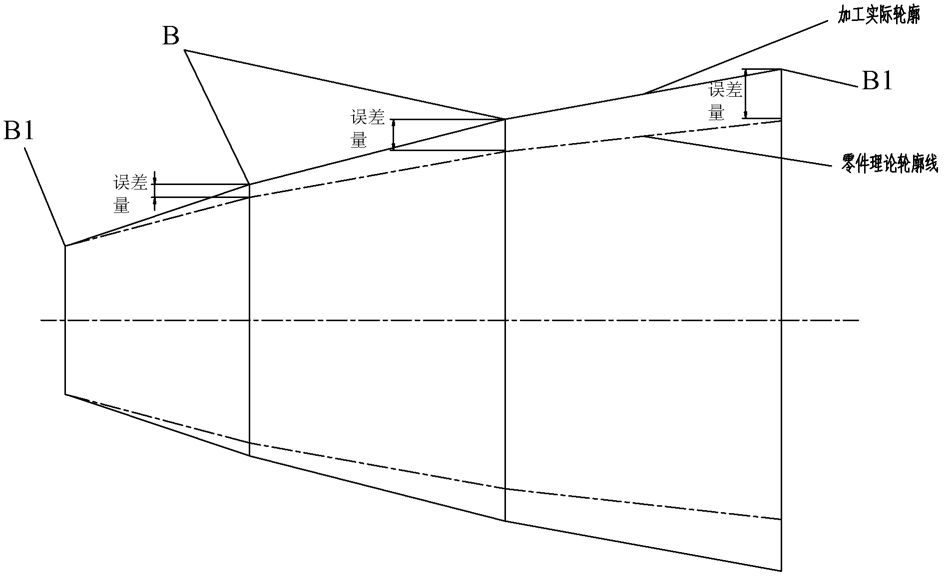
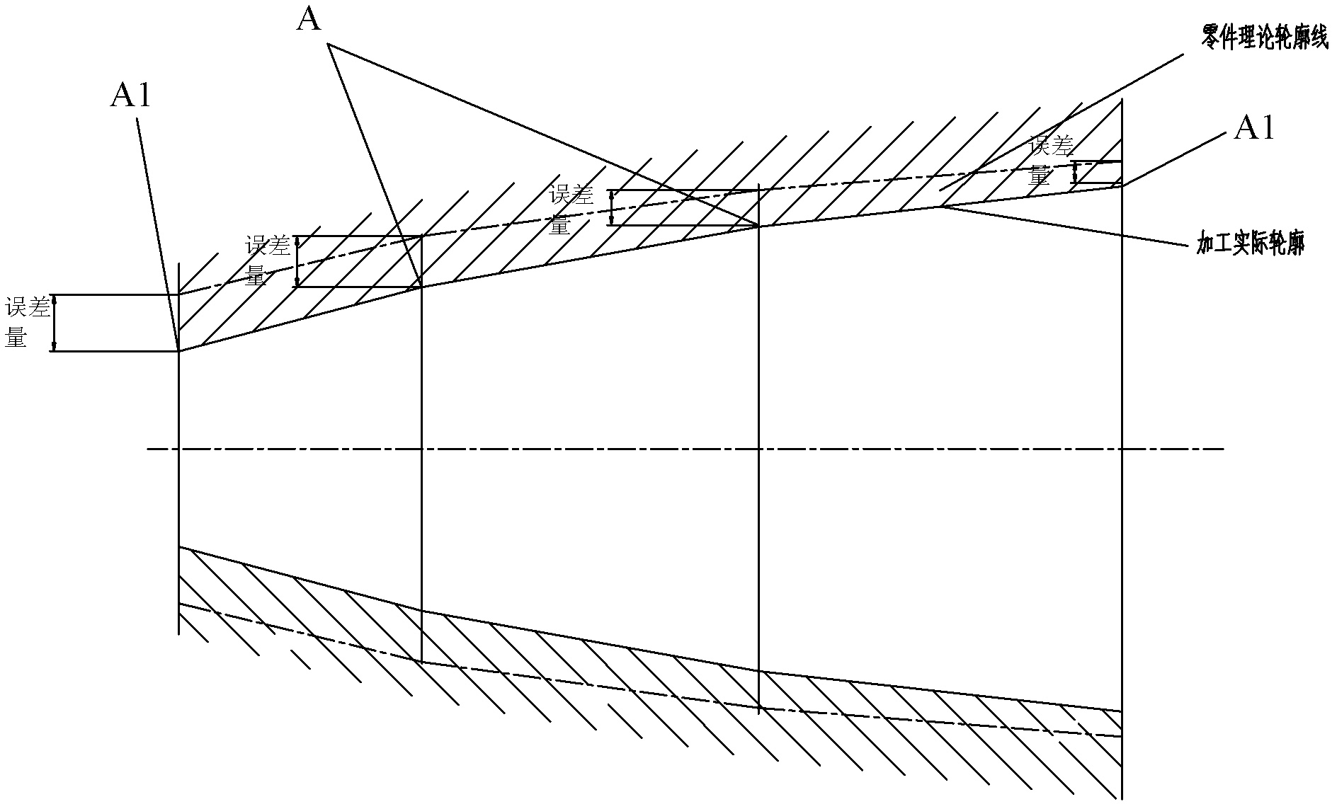
[0027] Step 2) Use a probe to measure the radius of the intersection point A of two adjacent contour line segments on the axial section of the inner hole of the rotating body part, and the radius of the two ends A1, the final theory of the intersection point A of the radius and the above contour line segment, and the two ends A1 Radius X 1 Compared to get the error amount δ 1 , the error amount δ 1 Stored in the address segment with continuous address bits in the memory of the lathe CNC system;

[0028] Step 3) Use the semi-finishing turning tool to perform semi-finishing on the rotary body parts after the rough machining in ...


PUM


Abstract

The invention discloses a self-adaptive compensation method for detecting the turning error of a large part of a rotary body, comprising the steps of: rough machining the part of the rotary body; measuring the radius of intersection of two adjacent contour line segments on an axial section of an inner hole of the part of the rotary body and en extent of error delta 1 of the radius of the two end points by a probe, performing semifinishing for the rough machined part of the rotary body, performing semifinishing for the semifinishing lathe tool by machining trajectory intersection and two end points with theoretical machining radius which is X1-delta 1 / 2, measuring the actual radiuses of the intersection (A) and two end points (A1) in the step 2) after semifinishing to obtain an extent of error delta1' of semifinishing; performing finish machining, wherein that finish machining lathe tool, the main shaft rotary speed of the tool and the feeding speed are identical to those of semifinishing. In the process of finish machining, a numerical control system of the lathe compensates the extent of error delta 1' of semifinishing. The invention solves the problem that in the machining process the machining error caused by tool wear exists, thereby greatly improving the machining precision of the large part of the rotary body.

Description

technical field [0001] The invention relates to the technical field of mechanical processing, in particular to a method for detecting and adaptively compensating for turning machining errors of large revolving body parts. technical background [0002] When large-scale rotary parts are processed on a lathe, the cutting length of the tool is one circle under the feed of each revolution of the part. After the cross-sectional profile of the part is processed, the cutting length of the part is πDL / s (D is the turning diameter, L is the length of the cutting section, s is the feed per revolution), it can be seen from the formula that the larger the diameter of the part, the longer the required cutting length, on the other hand, it can be seen from the processing experience of the factory that the problem of cutting tool wear It is especially prominent in the processing of large parts. Taking a large-scale rotary part manufactured by the factory as an example, the diameter of a par...

Claims


Application Information

Patent Timeline
IPC IPC(8): B23B5/00B23B25/06
Inventor 王晓兵胡大明赵凯白永雄
Owner HUBEI SANJIANG SPACE XIANFENG ELECTRONICS&INFORMATION CO LTD
Learn More