Fine pressure regulation type pneumatic pressurization cradle

A technology of pneumatic pressurization and cradle, applied in textiles and papermaking, drafting equipment, spinning machines, etc., can solve the problems of cumbersome installation procedures, attenuation of cradle pressure, inconsistent tightening force, etc., to reduce the installation workload, The effect of reducing labor intensity and stable pressure

Inactive Publication Date: 2012-05-02
四川成发普睿玛机械工业制造有限责任公司
View PDF9 Cites 4 Cited by
  • Summary
  • Abstract
  • Description
  • Claims
  • Application Information

AI Technical Summary

Problems solved by technology

The disadvantages of this pressure adjustment method are: ① Due to the large adjustment gap between the upper and lower mounting bracket end faces of the cradle, during the installation, pressure adjustment and fastening process of the cradle, due to the front and rear screws If the length is inconsistent, the cradle can rotate along the center of the holding tube, the angular position cannot be controlled consistently, and installation is relatively troublesome; ②In order to adjust the rated working pressure of the cradle, when tightening the front and rear screws, the tightening force is usually inconsistent, and The upper and lower mounting brackets are deformed due to excessive force, which makes the installation procedure of the lever-type pneumatic pressurized cradle cumbersome and difficult to adjust the rated pressure
Because only a single eccentric pin is used in this pressure regulating method, during the pressurization process of the handle, the roller (roller) connected to the handle and the pressure hook (pressure transmission crank) generate rolling friction, and the friction force will drive the eccentric pin Rotation, causing its eccentric position to change, causing the cradle pressure to decay
In addition, the cavity locking effect of the cradle seat and the clamping seat disclosed in ZL 200820053796.7 is poor

Method used


Image

  • Fine pressure regulation type pneumatic pressurization cradle
  • Fine pressure regulation type pneumatic pressurization cradle
  • Fine pressure regulation type pneumatic pressurization cradle

Examples


Embodiment Construction

[0016] The structure and working principle of the fine-tuning pneumatic pressurized cradle according to the present invention will be further described below in conjunction with the accompanying drawings.

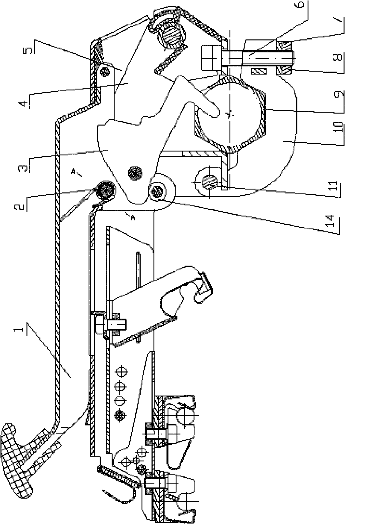
[0017] In this embodiment, the structure of the fine-tuning pneumatic pressurized cradle is as follows figure 1 As shown, it includes a cradle housing 5, a handle 1, a fixed card 4, a clamping card 10, a roller 14, a pressure transmission crank 3 and an eccentric pin assembly for pressure regulation.

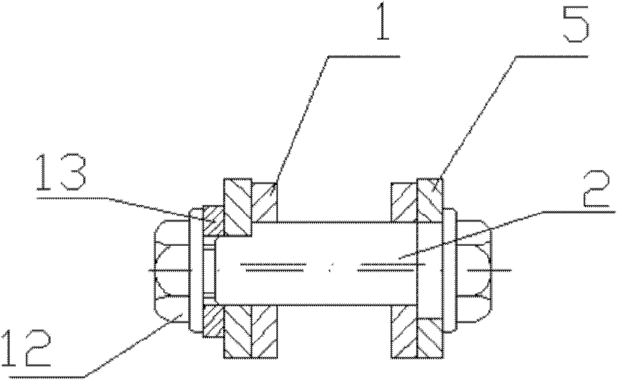
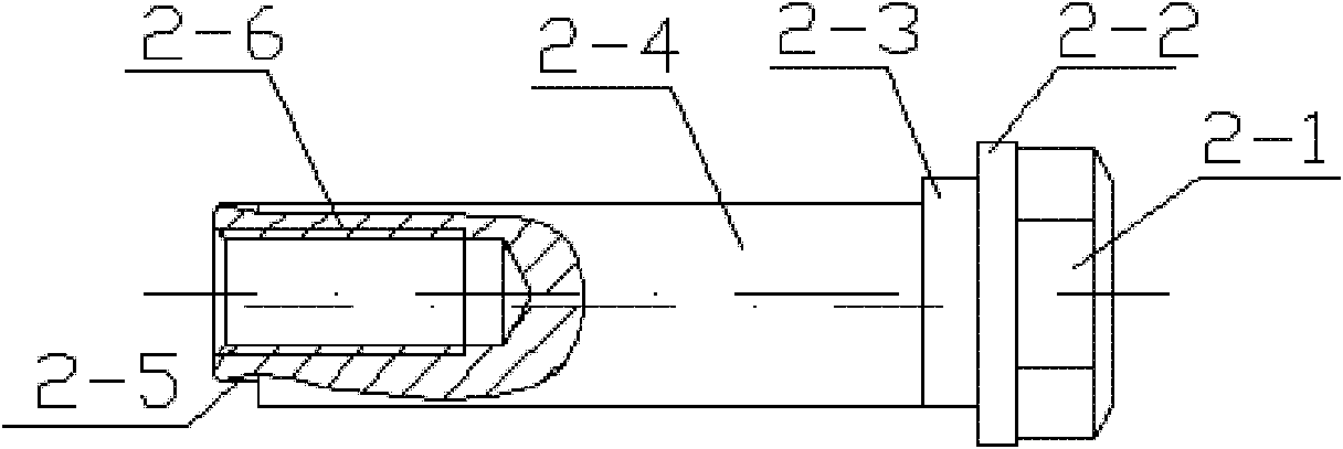
[0018] The structure of the eccentric pin assembly is as follows figure 2 As shown, it consists of eccentric pin 2, spring washer 13 and tightening screw 12. The structure of eccentric pin 2 is as follows image 3 As shown, the pin head 2-1, the combined washer 2-2, the first cradle shell hole matching section 2-3, the handle hole matching section 2-4 and the second cradle shell hole matching section 2- 5 components, the end of the second cradle shell hole matching sectio...


PUM


Abstract

The invention provides a fine pressure regulation type pneumatic pressurization cradle. The cradle comprises a cradle shell, a handle and a fixed clip which are hinged with the cradle shell, a clamping clip, a roller arranged on the handle, a pressure transmission crank and an eccentric pin component for regulating pressure, wherein one end of the clamping clip is hinged with the fixed clip, and the other end of the clamping clip is connected with the fixed clip through a bolt; the pressure transmission crank is hinged with the handle, and one end of the pressure transmission crank is contacted with the roller in pressurization; the eccentric pin component consists of an eccentric pin, a spring gasket and a screwing bolt, and is arranged on the hinging end of the handle and the cradle shell and positioned above the roller; and the eccentric pin component is assembled by the following way: one end of the eccentric pin passes through pores formed on the cradle shell and the handle and extends out, the spring gasket is sleeved on the eccentric pin and contacted with the cradle shell, and the spring gasket and the eccentric pin are fixed through the screwing bolt.

Description

technical field [0001] The invention belongs to the field of textile machinery, in particular to a pneumatically pressurized cradle of a spinning machine. Background technique [0002] Pneumatic pressurized cradle is an important part of the spinning machine. In the prior art, its pressure regulation methods are as follows: 1. Use the front and rear screws connecting the upper and lower decks of the cradle to "tighten before loosen" or "Front loosening and then tightening" method, respectively adjust the tightening force of the two screws to adjust the angular position of the deck on the cradle, and synchronously link the main body of the cradle to adjust the pressing force of the cradle (see ZL200920176564.5). The disadvantages of this pressure adjustment method are: ① Due to the large adjustment gap between the upper and lower mounting bracket end faces of the cradle, during the installation, pressure adjustment and fastening process of the cradle, due to the front and rea...

Claims


Application Information

Patent Timeline
Patent Type & Authority Applications(China)
IPC IPC(8): D01H5/46
Inventor 俞刚熊飞覃俊
Owner 四川成发普睿玛机械工业制造有限责任公司
Why Eureka
Try Eureka