Sliding cabin type multilevel damper equipped with power consumption and tuning particles

A particle damper and damper technology, which is applied to building components and anti-vibration, can solve the problems of limited collision energy consumption, poor multi-dimensional control effect, poor tuning ability, etc., to improve the control ability and the possibility of vibration , the effect of improving dynamic characteristics

Inactive Publication Date: 2012-05-02
BEIJING UNIV OF TECH
View PDF5 Cites 23 Cited by
  • Summary
  • Abstract
  • Description
  • Claims
  • Application Information

AI Technical Summary

Problems solved by technology

[0004] In order to solve the problems existing in the existing particle damping technology, such as difficult vibration of particles, poor multi-dimensional control effect due to particle stacking, limited collision energy dissipation capacity,...

Method used


Image

  • Sliding cabin type multilevel damper equipped with power consumption and tuning particles
  • Sliding cabin type multilevel damper equipped with power consumption and tuning particles
  • Sliding cabin type multilevel damper equipped with power consumption and tuning particles

Examples


Embodiment 1

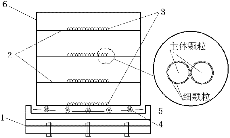
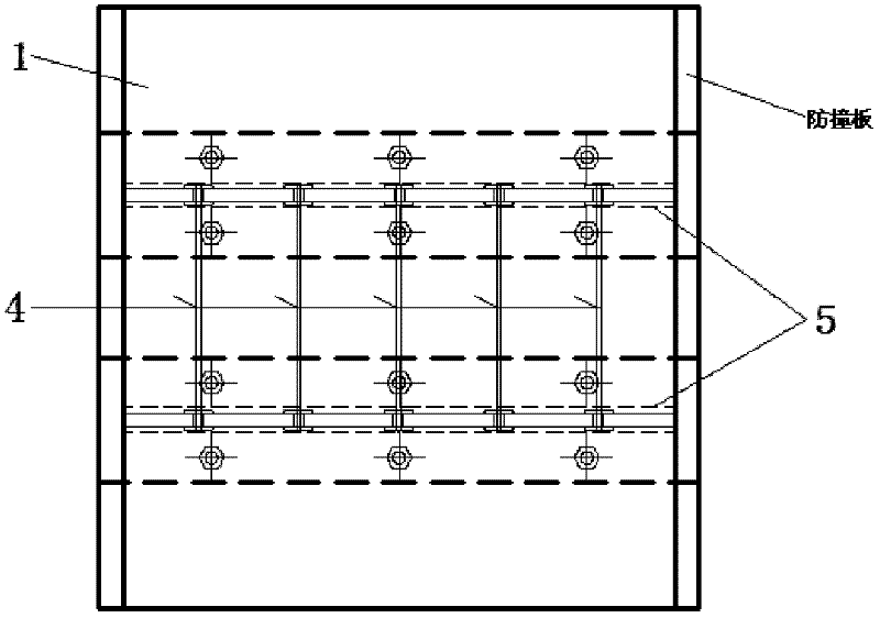
[0023] Such as Figure 1 to Figure 4 As shown, it is a sliding compartment type multi-stage distribution energy-tuning particle damper of the present invention, which mainly includes a damper anchoring device 1, a damper compartment plate 2, a multi-stage distribution damping particle group 3, and a directional sliding Support 4, slide groove 5 and damper cavity 6.

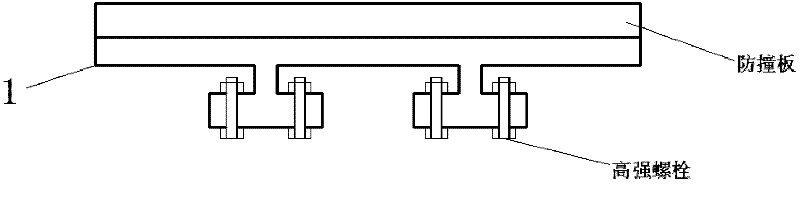
[0024] The damper anchoring device 1 is an I-shaped steel, which is connected to the anchor plate reserved by the structural member through high-strength bolts or directly embedded in the concrete with the high-strength bolts and then connected to the damper anchoring device. 5. The layout direction should be adjusted for the main direction layout of the first-order formation of the structure. The damper compartment plate 2 is a 5 mm smooth steel plate, which is connected to the damper cavity 6 by welding, and connected to the damper anchoring device 1 through the directional sliding support 4 . The one-way slid...

Embodiment 2

[0035] Such as Figure 1 to Figure 4 As shown, it is a sliding compartment type multi-stage distribution energy-tuning particle damper of the present invention, which mainly includes a damper anchoring device 1, a damper compartment plate 2, a multi-stage distribution damping particle group 3, and a directional sliding Support 4, slide groove 5 and damper cavity 6.

[0036]The damper anchoring device 1 is an I-shaped steel, which is connected to the steel plate reserved for the structure by welding. The damper anchoring device 1 is generally adjusted according to the arrangement direction of the sliding groove should be the main direction of the first-order formation of the structure. The damper bulkhead 2 is treated with 3mm inner surface bonded fine sand or bonded sandpaper. The damper compartment plate is connected with the damper cavity 6 by bolts to form a compartment. The damper cavity 6 is connected with the damper anchoring device 1 through the directional sliding su...


PUM

PropertyMeasurementUnit
Particle sizeaaaaaaaaaa
Tensile strengthaaaaaaaaaa
The average diameteraaaaaaaaaa

Abstract

The invention discloses a sliding cabin type multilevel damper equipped with power consumption and tuning particles for use in a building structure or a bridge structure, which belongs to the technical field of shock resistance and absorption and wind resistance in structure engineering. A damper cavity is in a rectangular or cylindrical shape; more than two damper cabin plates are arranged in the vertical direction of the damper cavity; a plurality of directional pulley supports are connected to the bottom surface of the damper cavity; the directional pulley supports can slide or roll in a sliding groove in a damper anchoring device; multilevel damper particle groups are placed uniformly in a single layer on each damper cabin plate; the multilevel damper particle groups are composed of major particles and fine particles; and the directional pulley supports can slide or roll on the sliding groove to enhance the impact effect of the damper particles by effect of wind and/or earthquake so as to tune structure frequency and dissipate kinetic energy of major structure.

Description

technical field [0001] The invention relates to a multi-stage particle damper connected with a main structure through a directional pulley support and has energy consumption and tuning functions, and belongs to the technical field of anti-seismic, shock-absorbing and wind-resistant structural engineering. Background technique [0002] In recent years, with the development of science and technology and the improvement of people's living standards, people have higher and higher requirements for the anti-seismic performance of structures and the comfort performance of structures against wind. Tuned mass damper (TMD) or tuned liquid damper (TLD) vibration reduction control technology has received extensive attention and has been applied in domestic and foreign projects because of its small change to the original structure, simple construction, and remarkable shock absorption effect. Particle damping technology, as a new type of tuning quality and energy consumption shock absorpt...

Claims


Application Information

Patent Timeline
IPC IPC(8): E04B1/98
Inventor 阎维明许维炳王瑾侯立群李德月
Owner BEIJING UNIV OF TECH
Why Eureka
Try Eureka