Flow meter of perforated plate

A technology of perforated plates and flow meters, which is applied to the volume/mass flow generated by mechanical effects, and the direction of fluid flow detection by measuring pressure difference, can solve the problems of flow field disorder, complex device structure, and reduced flow efficiency, and achieve fluid flow. Uniform field distribution, convenient installation and use, and the effect of reducing supporting costs

Active Publication Date: 2012-05-02
NANTONG CELLULOSE FIBERS CO LTD
View PDF5 Cites 26 Cited by
  • Summary
  • Abstract
  • Description
  • Claims
  • Application Information

AI Technical Summary

Problems solved by technology

The purpose of the curved part of the flowmeter is to reduce the liquid effusion in the pipeline, which is more beneficial than the single-orifice flowmeter installed on the straight pipeline, but the structure of the device is too complicated, which will easily lead to a drop in pipeline pressure and a decrease in flow efficiency
[0004] Ordinary perforated plates have many uniformly distributed small holes with the same diameter on one plate. While improving the shortcomings of single-orifice plates with high resistance, there are still other problems: fluid fluctuations in high-pressure areas, flow fields in low-pressure areas disorder, which leads to signal fluctuations and greatly affects the ...

Method used


Image

  • Flow meter of perforated plate
  • Flow meter of perforated plate
  • Flow meter of perforated plate

Examples


Embodiment 1

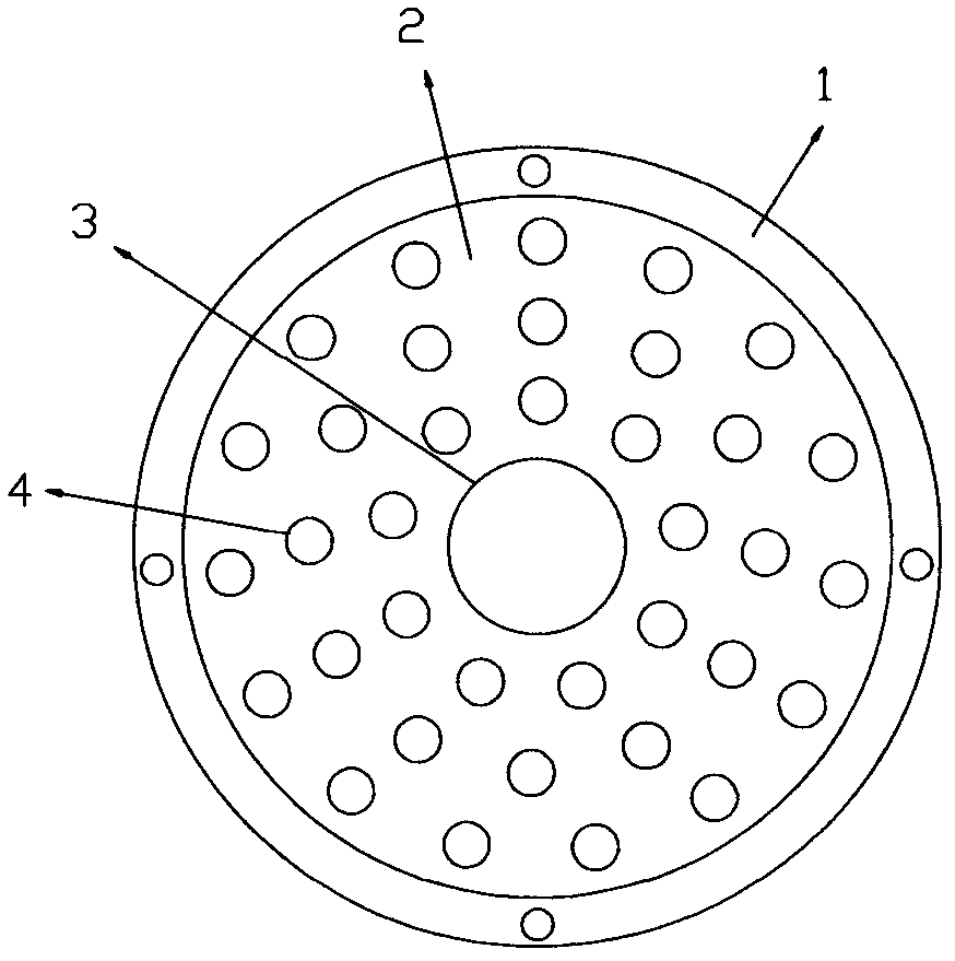
[0028] As attached figure 1 , Attached Figure 4 As shown, the diameter of the circular plate substrate 2 is equal to the diameter of the pipe 6, and the opening rate of the holes on the substrate 2 is 20%; the substrate 2 is type ①: the center of the substrate 2 has a large circle Holes 3 and other parts of the substrate 2 are evenly arranged with several small round holes 4, the diameter of the small round holes 4 is 2 mm, and the diameter of the large round hole 3 is 3 times the diameter of the small round hole 4. The flowmeter is the first type: direct-reading inclined tube differential pressure flowmeter 8. The flange sheet 1 of the perforated plate is fixedly connected in the pipeline 6 through the pipeline flange.

Embodiment 2

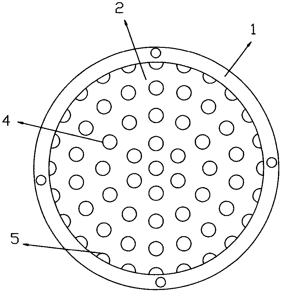
[0030] As attached figure 2 , Attached Figure 5 As shown, the diameter of the substrate 2 is equal to the diameter of the pipe 6, and the opening rate of the holes on the substrate 2 is 30%; the substrate 2 is the second type: the substrate 2 is evenly arranged with several pieces of the same diameter Small round hole 4, the diameter of the small round hole 4 is 3mm, but the outermost small round hole 4 intersects the periphery of the base plate 2 and appears as a non-circular hole 5; the flow meter is the second type: the differential pressure sensor 9 and The secondary meter 10 is connected together with an indirect reading flow meter. The perforated plate is fixedly connected in the pipeline 6 through a sleeve. When the perforated plate is installed in the pipe 6, the center of a non-circular hole 5 is directly below the center of the pipe.

Embodiment 3

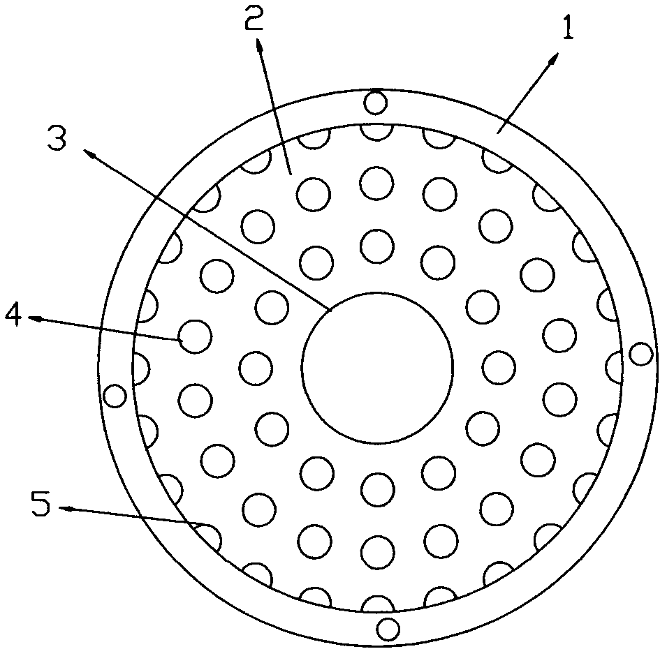
[0032] As attached image 3 , Attached Image 6 As shown, the diameter of the circular substrate 2 of the perforated plate is slightly larger than the diameter of the pipe 6, and its error is smaller than the diameter of the small circular hole 4; the opening rate of the holes on the substrate 2 is 45%; the substrate 2 is the third Variety, the center of the substrate 2 has a large circular hole 3, and other parts of the substrate 2 are evenly arranged with several small circular holes 4, the diameter of the small circular holes 4 is 4mm, but the outermost small circular hole 4 intersects the periphery of the substrate 2 It appears as a non-circular hole 5, the diameter of the large round hole 3 is 5 times the diameter of the small round hole 4; the flow meter is the third type: the differential pressure switch 11, the differential pressure sensor 9 and the secondary instrument connection 10 are connected together Indirect reading flowmeter. The perforated plate is fixedly con...


PUM

PropertyMeasurementUnit
Diameteraaaaaaaaaa
Diameteraaaaaaaaaa

Abstract

The invention provides a flow meter of a perforated plate, which comprises the perforated plate and the flow meter. A substrate of the perforated plate is in a circular shape. The perforation rate f the perforated plate ranges from 10% to 60%. The substrate has three categories with uneven hole structures. A large circular hole is arranged at the centre position of a preferential substrate, a plurality of small circular holes are evenly distributed on the other positions of the substrate, the small circular holes arranged on the outmost periphery intersect with the periphery of the substrate to form non-complete circular holes. The diameter of the large circular hole is two to ten times of the diameter of the small circular holes. The flower meter can be chosen from three categories: 1 a direct-reading type pipe chute differential-pressure flow meter, 2 an indirect reading flow meter connected with a secondary meter through a differential-pressure sensor and 3 an indirect reading flowmeter connected with a secondary meter through a differential-pressure switch and a differential-pressure sensor. The flow meter is small in volume, convenient to install, high in measurement accuracy, small in flow resistance of fluid, less in liquid accumulation in a pipeline and especially suitable for measuring flow of vapor, combustible fluid, explosive fluid, corruptible fluid and dirty fluid.

Description

Technical field [0001] The invention relates to a device for measuring the flow of fluid in a pipeline, especially a flow meter composed of a porous plate. Background technique [0002] The flow measurement of the fluid in the pipeline laid in the fluid engineering requires the use of a flowmeter, usually a float flowmeter, an orifice (single orifice) flowmeter, and a venturi flowmeter. These flow rates have the disadvantages of high meter price, large volume, large resistance to fluid, low measurement accuracy or inconvenient installation. Especially when online monitoring of the flow of many pipelines is required, the limited space on site often makes it impossible to install and use existing flow meters. [0003] The patent specification with the patent number 200910176227.0 discloses a "flow meter and flow control device". The flow meter includes a first perforated plate. The first perforated plate is arranged on the first curved part of the flow path and is opposite to the fi...

Claims


Application Information

Patent Timeline
IPC IPC(8): G01F1/36
Inventor 杨占平周鹏晨高春红黄建新陆书明褚红娟赵从涛
Owner NANTONG CELLULOSE FIBERS CO LTD
Why Eureka
Try Eureka