
Method for real-time measurement of multipoint temperatures based on fluorescence optical fiber temperature sensor

A temperature sensor and fluorescent fiber technology, applied in the field of temperature sensors, can solve the problems of inability to obtain at the same time, high cost, affecting the stability of temperature measurement, etc., to achieve real-time positioning measurement, reduce system costs, and achieve the effect of simultaneous measurement

Inactive Publication Date: 2012-05-02
TSINGHUA UNIV
View PDF4 Cites 16 Cited by
  • Summary
  • Abstract
  • Description
  • Claims
  • Application Information

AI Technical Summary

Problems solved by technology

However, the disadvantages of this method are: on the one hand, the complex dynamic coupling device introduces dynamic coupling errors, which affects the stability of temperature measurement;
[0005] In addition, multi-point temperature measurement can also be realized by referring to the time-division multiplexing method in optical fiber communication, but this method requires the use of multiple excitation light sources and a precise time synchronization system, and the system is complex and expensive

Method used


Image

  • Method for real-time measurement of multipoint temperatures based on fluorescence optical fiber temperature sensor
  • Method for real-time measurement of multipoint temperatures based on fluorescence optical fiber temperature sensor
  • Method for real-time measurement of multipoint temperatures based on fluorescence optical fiber temperature sensor

Examples


Embodiment

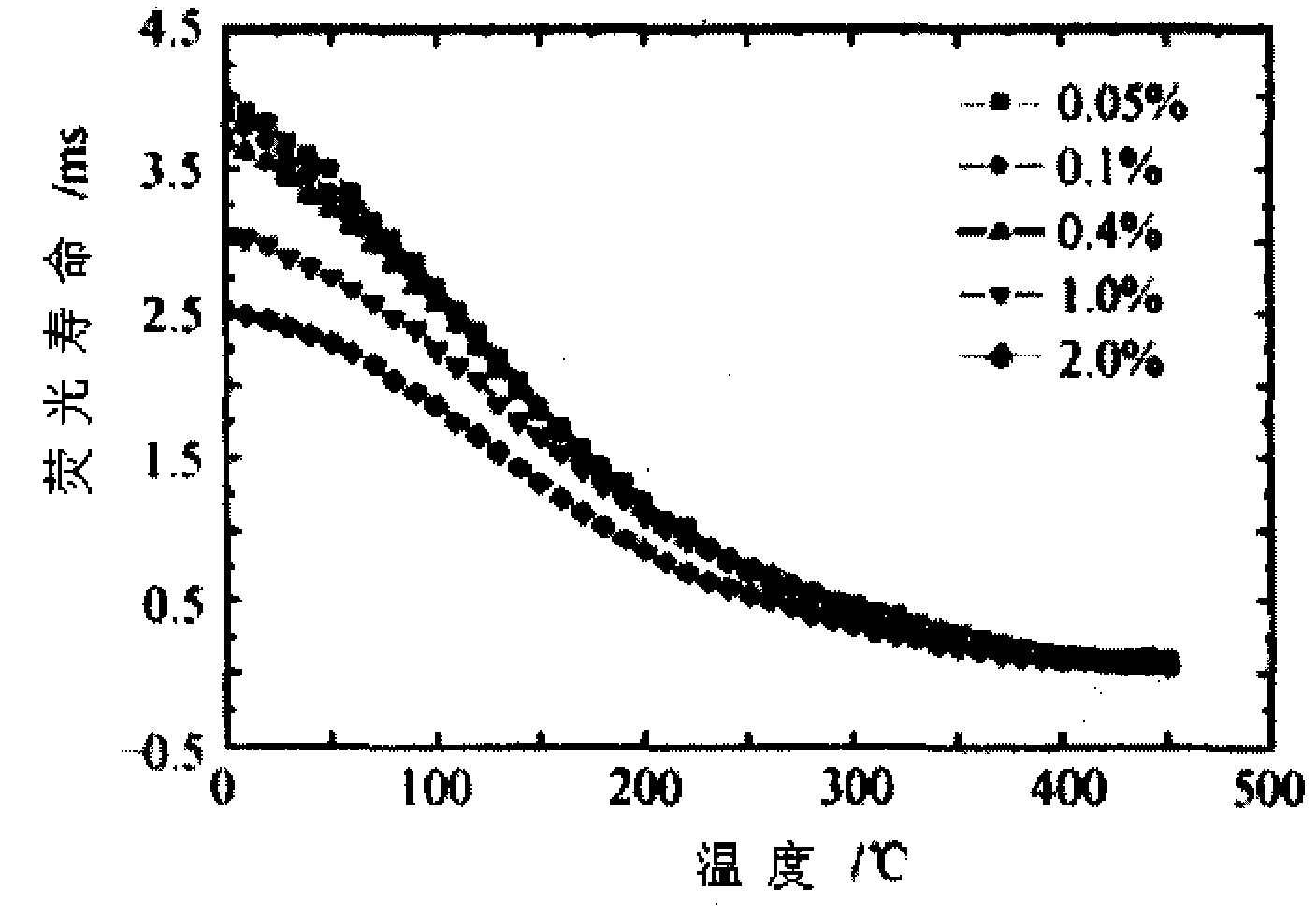
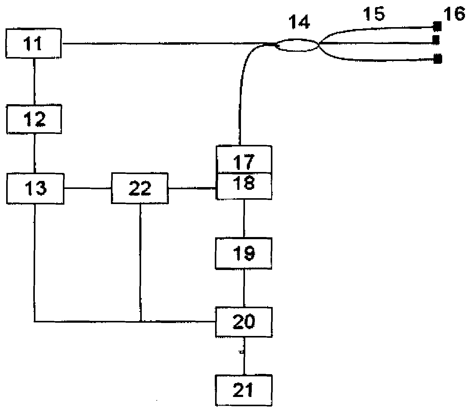
[0106] An implementation example of the present invention is described in detail below (as image 3 shown), the optical fiber probe (Q=3) uses different concentrations of fluorescent substances for multi-point real-time temperature measurement. Among them, 11-light-emitting diode (excitation light source) with pigtail output, 12-drive circuit, 13-modulation signal source, 14-fiber coupler, 15-quartz optical fiber, 16-end with Cr 3+ Ion-doped sapphire fiber probe (fiber probe) (Cr 3+ Doping concentration, that is, the atomic concentration is 0.4%, 1.0%, and 2.0%, respectively), 17-optical filter, 18-photomultiplier tube and working circuit (photodetector), 19-low-pass filter, 20-band mode Number conversion MCU ATmega16, 21-PC, 22-phase shifter. Different doping Cr 3+ The fluorescence lifetime of sapphire single crystal fiber probe with ion concentration varies with temperature under different doping concentrations (Ye Linhua, Zhou Xiaofen, Zhang Jinfeng, et al. LED pumped sa...


PUM


Abstract

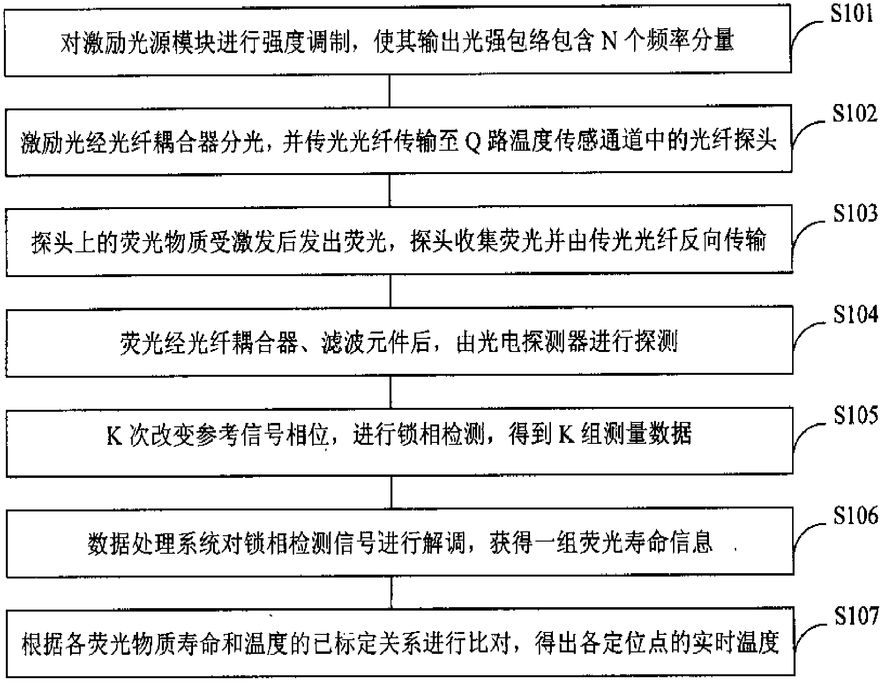
The invention discloses a method for real-time measurement of multipoint temperatures based on a fluorescence optical fiber temperature sensor, and belongs to the field of temperature sensors. The method is characterized in that: an excitation light source module is subjected to intensity modulation, thus the excitation light source module outputs the excitation light which has the light intensity comprising N frequency components and excites the fluorescent substances in Q channel optical fiber probes; and a phase lock detection technique is adopted to carry out demodulation on the collectedfluorescence signals through K groups of data obtained by phase shift so as to obtain the fluorescence lifetime of each measurement point, and the temperatures of the corresponding points are furtherobtained. According to the method disclosed by the invention, multi-point measurement can be realized only by adopting a single excitation light source and a signal detecting and processing module, and the advantages of simple and compact structure, low system cost and capability of real-time positioned measurement of multipoint temperatures can be realized.

Description

technical field [0001] The invention belongs to the field of temperature sensors, in particular to a method for measuring multi-point temperatures in real time based on a fluorescent optical fiber temperature sensor. Background technique [0002] Compared with traditional temperature sensors, optical fiber temperature sensors have many advantages, such as: light waves are not affected by electromagnetic interference; optical fiber has a wide operating frequency and a large dynamic range, and is a low-loss transmission line; the optical fiber itself is uncharged, small in size and light in weight , easy to bend, good radiation resistance. Therefore, the fiber optic temperature sensor is especially suitable for use in harsh environments such as flammable, explosive, strictly limited space, and strong electromagnetic interference, which solves the problem of temperature measurement that cannot be solved by traditional methods. Among them, the fluorescent optical fiber temperat...

Claims


Application Information

Patent Timeline
IPC IPC(8): G01K11/32
Inventor 杨昌喜孔令杰李军肖晓晟
Owner TSINGHUA UNIV
Learn More