Steady flow pumping test device for on-line full-hole continuous detection and detection method thereof

A technology of pumping test and steady flow, which is applied in the field of outdoor test of permeability coefficient, can solve the problems that the distribution of permeability coefficient of rock and soil layer along the buried depth of pumping well hole cannot be obtained, cannot meet the needs of field engineering, and lose pumping test, etc., and achieve Good promotion and use value, low test cost, high measurement accuracy and sensitivity

Inactive Publication Date: 2012-05-02
HUNAN UNIV OF SCI & TECH
View PDF4 Cites 17 Cited by
  • Summary
  • Abstract
  • Description
  • Claims
  • Application Information

AI Technical Summary

Problems solved by technology

[0003] (1) Although the average permeability coefficient of the formation in the seepage area can be accurately calculated, the distribution of the permeability coefficient of the rock and soil layer along the buried depth of the pumping well hole cannot be obtained, so that it is impossible to accurately find out the small area with a large permeability coefficient according to the pumping test The buried depth position and seepage volume of the section cannot meet the needs of the current site engineering
[0004] (2) When there are multiple aquifers and different depths of boreholes are used for layered pumping tests, due to the complex groundwater connection network between different test sections, hydraulic connections occur, and the water volume in the pumping test test section is easily disturbed. Cause test error, sometimes the test error is very large, lost the significance of pumping test

Method used


Image

  • Steady flow pumping test device for on-line full-hole continuous detection and detection method thereof
  • Steady flow pumping test device for on-line full-hole continuous detection and detection method thereof
  • Steady flow pumping test device for on-line full-hole continuous detection and detection method thereof

Examples


Embodiment Construction

[0025] The present invention will be further described in detail below in conjunction with the accompanying drawings and embodiments.

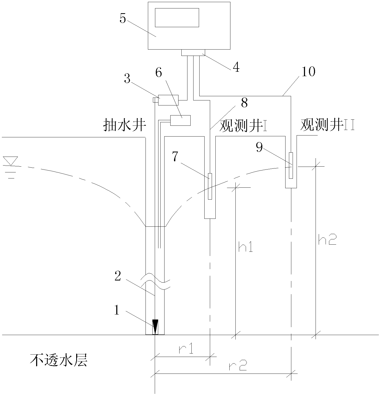
[0026] see figure 1 , in this embodiment, a flow meter probe 1 is placed at the bottom of the test pumping well, and the flow meter probe 1 adopts an ultrasonic Doppler flow meter probe; a water level monitor 7 and a water level monitor 7 are placed in the test observation well I and observation well II respectively. The water level monitor 9; the current meter probe 1 is connected to the servo motor 3 through the cable 2, and its signal output terminal is connected to the photoelectric isolator 4 through the signal line in the cable 2; the signals of the water level monitor 7 and the water level monitor 9 The output end is also connected to the photoelectric isolator 4 through the signal line 8 and the signal line 10 respectively, and the output end of the photoelectric isolator 4 is connected to the input end of the microcomputer system 5; a...


PUM


Abstract

The invention discloses a steady flow pumping test device for on-line full-hole continuous detection and a detection method thereof. The test device comprises a flow meter probe arranged at the bottom of a pumping well used for tests, and two water level monitors respectively arranged in an inspection well I and an inspection well II used for tests; the flow meter probe is connected to a servo motor through a cable, and a signal output end of the flow meter probe is connected with a photoisolator through a signal wire in the cable; signal output ends of the two water level monitors are also respectively connected with the photoisolator through signal wires, and an output end of the photoisolator is connected with an input end of a microcomputer system; and the pumping well is provided with a pumping system. According to the invention, after the measured flow velocity and water level electrical signals are sent to the microcomputer system, data processing and analysis are carried out to obtain the distribution situation of rock and soil bed permeability coefficients along a pumping well hole within the scope of burial depth. With the device and detection method disclosed by the invention, the permeability coefficients of rock and soil beds can be accurately, sensitively and conveniently measured.

Description

technical field [0001] The invention belongs to the technical field of outdoor test of permeability coefficient of rock and soil layer in geotechnical engineering investigation, and in particular relates to a steady flow pumping test equipment and a detection method thereof for online full-hole continuous detection. Background technique [0002] In the field of engineering exploration, the permeability coefficient of the formation is an important hydrogeological parameter. In order to measure the permeability coefficient of the formation, two methods are mainly used: indoor test and field test. The indoor test generally includes the constant head method and the variable head method. For Coarse-grained soils or layered soils are easily affected by factors such as sampling representativeness, sampling disturbance, and scale effects, and the test results generally have large errors; however, field tests are carried out through water injection tests and pumping tests on test str...

Claims


Application Information

Patent Timeline
Patent Type & Authority Applications(China)
IPC IPC(8): G01N15/08
Inventor 陈伟张联志王志斌崔大田朱建群安永林
Owner HUNAN UNIV OF SCI & TECH
Why Eureka
Try Eureka