
High-power microwave impulse shield

A high-power microwave and protective cover technology, which is applied to waveguide-type devices, electrical components, circuits, etc., can solve problems such as inability to protect high-power microwaves, damage to active antennas, and damage to limiters, and achieves obvious out-of-band suppression. The effect of reducing the area and reducing the 3dB bandwidth

Active Publication Date: 2014-01-08
CHINA SHIP DEV & DESIGN CENT
View PDF2 Cites 0 Cited by
  • Summary
  • Abstract
  • Description
  • Claims
  • Application Information

AI Technical Summary

Problems solved by technology

[0004] At present, radar protection mainly uses the limiter at the rear end of the antenna to limit the high-power signal, but it cannot protect high-power microwaves for the following reasons: First, the limiter generally uses the breakdown of protective devices such as gas discharge tubes. It plays the role of protection, and its response time is more than tens of ns, which cannot protect the high-power microwave with ns-level rising edge time; secondly, after the high-power microwave is reflected by the large area array antenna and superimposed gain, the instantaneous power rises An order of magnitude, the limiter may be damaged; in addition, many sensitive equipment antennas are active antennas, and high-power microwaves may have caused damage to the active antenna before the limiter works.
[0005] So far, there is no specific protection against high power microwaves

Method used


Image

  • High-power microwave impulse shield
  • High-power microwave impulse shield
  • High-power microwave impulse shield

Examples


Embodiment Construction

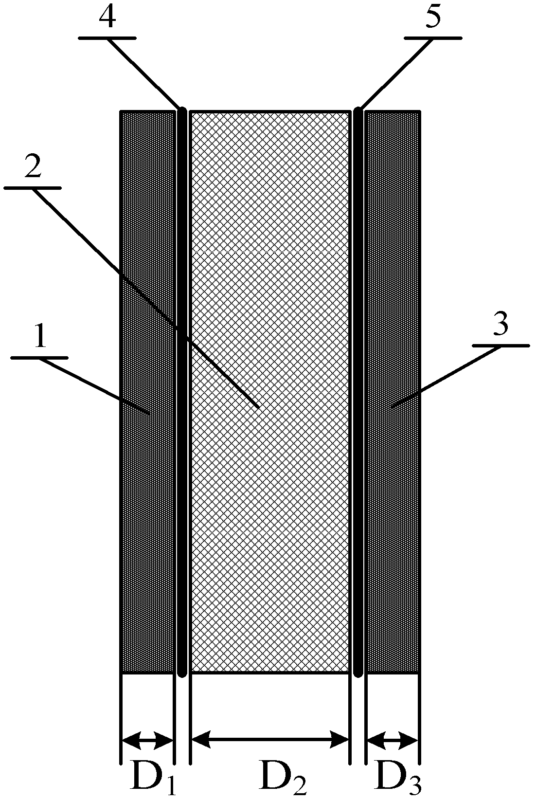
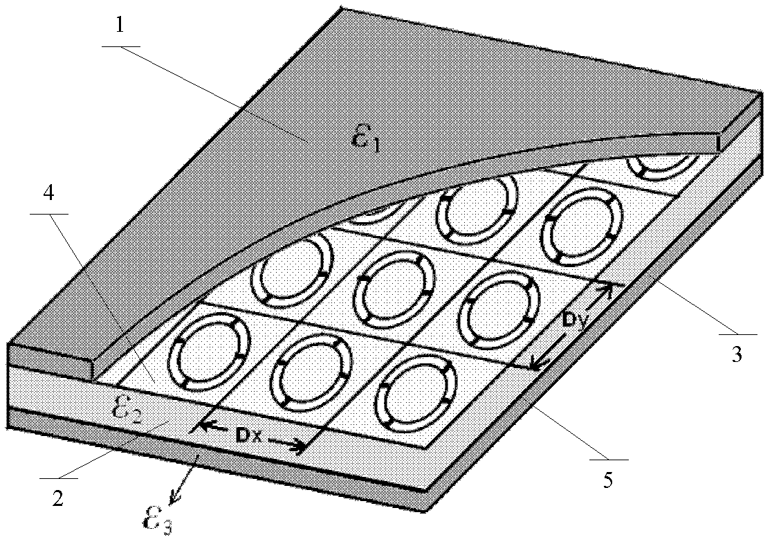
[0030] figure 1 It is a side view of an embodiment of the present invention, which includes at least 2 layers of bandpass frequency selective plates, adjacent bandpass frequency selective plates are parallel to each other and filled with loading medium between them; each bandpass frequency selective plate is a conductive plate, and The distribution has periodic small units. In the present embodiment, the copper clad boards of 2 PCB boards are selected as the bandpass frequency selection boards, namely 4 and 5 in the figure; 1 and 3 are fixed mediums in the figure, and the present embodiment adopts the substrate of the PCB board as the fixed medium, so that 1 4 and 5 form a complete PCB board, 5 and 3 form a complete PCB board, and the fixed medium acts as a fixed bandpass frequency selection board. Since the copper clad plate is very thin, it is very easy to deform without a fixed medium, and the response characteristics will be affected after deformation. ; Between 4 and 5 i...


PUM


Abstract

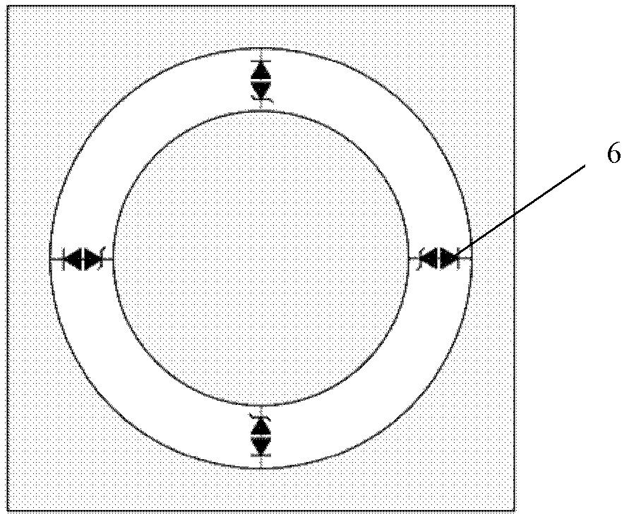
The invention provides a high-power microwave impulse shield. The high-power microwave impulse shield is characterized by comprising at least two layers of band pass frequency selecting plates, wherein the adjacent band pass frequency selecting plates are parallel with each other and a loading medium is filed between the adjacent band pass frequency selecting plates; each band pass frequency selecting plate is a conductive plate, and periodic small units are distributed on each band pass frequency selecting plate; hollowed-out patterns are etched on each small unit; each small unit is divided into at least two conductive regions which are mutually separated by the hollowed-out patterns; and at least one TVS (transient voltage suppressor) is welded among mutually separated conductive regions in the same small unit or among different small units. By utilizing different electromagnetic properties of the TVS under different power microwave signals, the TVS can keep high-power microwave impulse electromagnetic wave out of the shield on the premise that the transmission of a normal small signal is not affected, thereby preventing a high-power microwave impulse from entering into sensitive electronic equipment to generate destruction.

Description

technical field [0001] The invention belongs to the technical field of strong electromagnetic pulse protection, and in particular relates to a high-power microwave pulse protective cover suitable for L, S, and C band radars and the periphery of communication equipment antennas. Background technique [0002] With the development of electromagnetic pulse technology, the high-power microwave pulse radiation field intensity generated by high-power microwave weapons reaches hundreds of kV / m, the pulse rise time is as short as possible, and the pulse duration can reach tens of ns to tens of us. Radar and communication electronic equipment in the S and C frequency bands are becoming more and more harmful. The electromagnetic pulse voltage and current induced by high-power microwaves on electronic equipment can instantly breakdown or burn communication equipment, so there is an urgent need for electronic equipment in this frequency band Protect against high power microwaves. [000...

Claims


Application Information

Patent Timeline
Patent Type & Authority Patents(China)
IPC IPC(8): H01P1/20
Inventor 邓峰易学勤郑生全丁锦超方重华刘其凤
Owner CHINA SHIP DEV & DESIGN CENT
Learn More