Alternating current (AC) ice melting system for traction network of electrified railway

A technology for electrified railways and traction nets, applied in the installation of electrical components, cables, and overhead installations, can solve problems such as low power utilization, high cost of rectification devices, and low safety and reliability, and achieve high energy utilization and equipment High reliability, high safety and reliability effect

Inactive Publication Date: 2012-05-02
CHINA RAILWAY ERYUAN ENG GRP CO LTD
View PDF6 Cites 6 Cited by
  • Summary
  • Abstract
  • Description
  • Claims
  • Application Information

AI Technical Summary

Problems solved by technology

At present, the most common way to remove the icing of the traction net conductor is to manually beat the ice, which is very easy to cause mechanical damage to the catenary and additional wires
In addition, some units have proposed an AC ice-melting method in which a large resistor is connected in series in the traction network to control the current. This method has a low utilization rate of electric energy
Some units have proposed the method of directly short-circuiting the traction network and using the short-circuit current to melt ice. The large short-circuit current generated by this method will damage the electrical equipment, which is difficult to control and has low safety and reliability.
Some units have proposed a DC ice-melting method in which a rectifier is installed in the traction network. The cost of the rectifier is relatively high, and the rectifier is easily damaged.

Method used


Image

  • Alternating current (AC) ice melting system for traction network of electrified railway
  • Alternating current (AC) ice melting system for traction network of electrified railway
  • Alternating current (AC) ice melting system for traction network of electrified railway

Examples


Embodiment 1

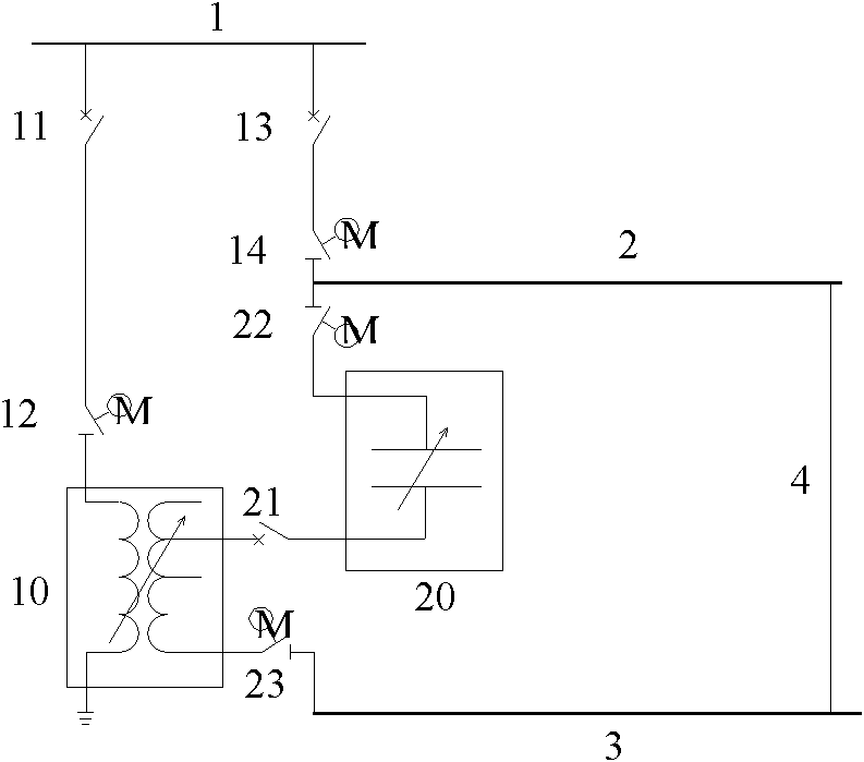
[0024] Such as figure 1 shown. The step-down transformer 10 and capacitive electrical equipment 20 are installed in or near the traction substation. The high voltage side of the step-down transformer 10 is connected to the 27.5kV bus 1 of the traction substation through the first isolating switch 12 and the first circuit breaker 11 . The low-voltage side of the step-down transformer 10 is first connected to the capacitive electrical equipment 20, and then connected to the catenary 2, other conductors 3 of the traction network and the connecting conductor 4 to form an ice-melting circuit.

[0025] During normal operation without icing on the catenary 2, the first circuit breaker 11, the first isolating switch 12, the third circuit breaker 21, the third isolating switch 22, and the fourth isolating switch 23 are all in the off state. When icing occurs on the catenary 2 and ice-melting work needs to be carried out, the operation steps of this embodiment are as follows:

[0026]...

Embodiment 2

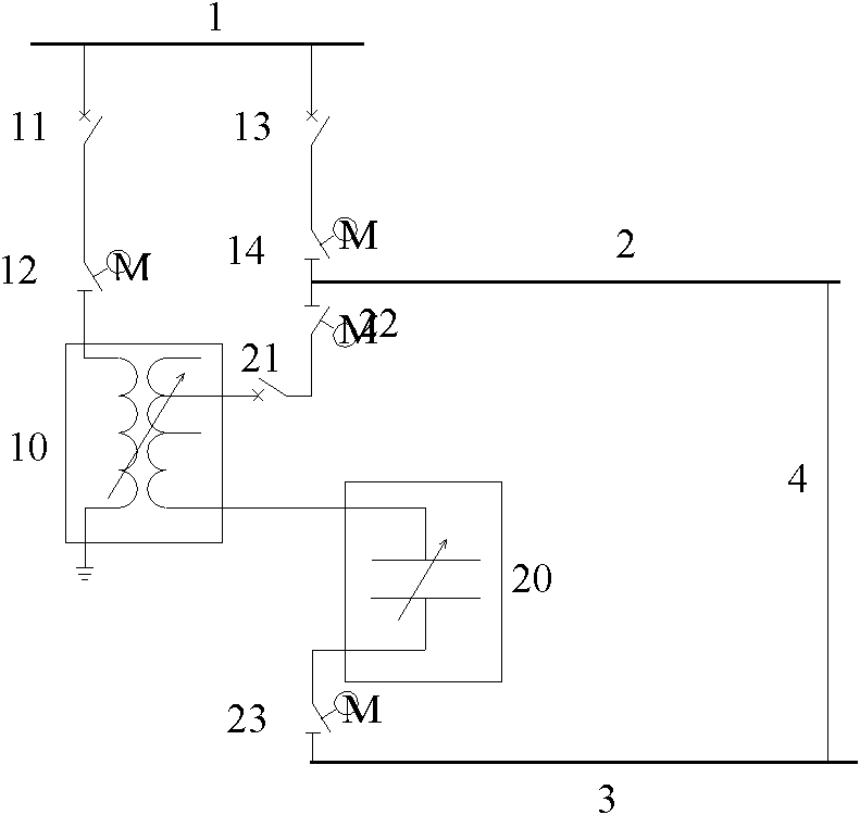
[0035] Such as figure 2 shown. The step-down transformer 10 and the capacitive electrical equipment 20 are installed in or near the traction substation. The high voltage side of the step-down transformer 10 is connected to the 27.5kV bus 1 of the traction substation through an isolating switch 12 and a circuit breaker 11 . The low-voltage side of the step-down transformer 10 is first connected to the catenary 2, the connecting conductor 4 and other conductors 3 of the traction network, and then connected to the capacitive electrical equipment 20 to form an ice-melting circuit.

[0036]During normal operation without icing on the catenary 2, the first circuit breaker 11, the first isolating switch 12, the third circuit breaker 21, the third isolating switch 22, and the fourth isolating switch 23 are all in the off state. When icing occurs on the catenary 2 and ice-melting work needs to be carried out, the operation steps of this embodiment are as follows:

[0037] Open the s...

Embodiment 3

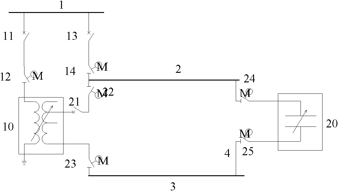
[0046] Such as image 3 shown. The step-down transformer 10 is installed in or near the traction substation, and the capacitive electrical equipment 20 is installed near the split phase at the end of the power supply arm (or in or near the divisional substation). The low-voltage side of the step-down transformer 10 is first connected with the catenary 2, and then connected with the other conductors 3 of the traction network through the capacitive electrical equipment 20 and the connecting conductor 4 to form an ice-melting circuit.

[0047] During normal operation without ice coating on the catenary 2, the first circuit breaker 11, the first isolating switch 12, the third circuit breaker 21, the third isolating switch 22, the fourth isolating switch 23, the fifth isolating switch 24, the first 6 The isolation switches 25 are all in the disconnected state.

[0048] When icing occurs on the catenary 2 and ice-melting work needs to be carried out, the operation steps of this em...


PUM


Abstract

The invention provides an alternating current (AC) ice melting system for a traction network of an electrified railway. The AC ice melting system is provided with a step-down transformer and capacitive electrical equipment; the current flowing through the traction network is adjusted by adjusting output voltage of the step-down transformer and impedance of the capacitive electrical equipment, and ice coating is molten by virtue of Joule heat generated in the event that the current flows through a lead; and a complete set of device has the advantages of small electrical capacity and high energy utilization ratio. The AC ice melting system comprises the step-down transformer (10), the capacitive electrical equipment (20), a circuit breaker and an isolating switch, wherein, the high-voltage side of the step-down transformer (10) is connected to a bus (27.5kV) of a traction substation through the isolating switch and the circuit breaker; and the capacitive electrical equipment (20), a contact network (2) and a bonding conductor (4) are connected with other conductors (3) of the traction network to form an ice melting circuit through the circuit breaker and the isolating switch at the low-voltage side of the step-down transformer (10).

Description

technical field [0001] The invention relates to an electrified railway traction network, in particular to an AC ice-melting system for an electrified railway traction network with a step-down transformer and capacitive electrical equipment. Background technique [0002] Electrified railway traction network includes conductors such as catenary, rails and additional wires (return line, positive feeder, etc.). At the end of the power supply arm of the double-track electrified railway, there is usually a partition station with an uplink and downlink parallel switch. Catenary is an important traction power supply facility that provides electric energy to EMUs and electric locomotives. When the catenary is covered with ice, the pantographs on the EMUs and electric locomotives will not be in normal contact with the contact wires, resulting in power loss and failure to operate. It may also cause serious accidents such as catenary dancing, pillars toppling, and even catenary collaps...

Claims


Application Information

Patent Timeline
Patent Type & Authority Applications(China)
IPC IPC(8): H02G7/16
Inventor 楚振宇陈刚陈纪纲袁勇徐剑李剑潘英宋兵林宗良汪秋宾
Owner CHINA RAILWAY ERYUAN ENG GRP CO LTD
Why Eureka
Try Eureka