Switch tube driving circuit based on integrated driving chip

A technology of integrated drive and switching tube, applied in the circuit field, can solve the problems of large energy consumption, distortion, and high energy consumption of the drive circuit

Inactive Publication Date: 2012-05-02
HANGZHOU HENGSHENG ELECTRONICS TECH
View PDF3 Cites 28 Cited by
  • Summary
  • Abstract
  • Description
  • Claims
  • Application Information

AI Technical Summary

Problems solved by technology

[0002] Traditional high-side power switch tube drive circuit, one (can be used with figure 1 (shown) is to use the principle of capacitor boosting to connect a power diode between the source of the high-side power switch and the point where there is always voltage to the ground connected to it, so that the source of the high-side power switch is turned off Due to the reverse non-conduction of the diode, it is disconnected from the point where there is always voltage to the ground, and at the same time, the negative pole of the boost capacitor is directly grounded through a resistor, so as to complete the charging of the boost capacitor. In this way, the connection resistance and power A large amount of energy will be consumed in the diode, resulting in too much power consumption of the drive circuit
The other is to use a transformer to achieve signal isolation and transmission, but since the transformer can only transmit AC signals, when the duty cycle of the control signal PWM is small or large, distortion will occur after transmission through the transformer, so this type of drive circuit Only suitable for applications with a duty cycle around 0.5

Method used


Image

  • Switch tube driving circuit based on integrated driving chip
  • Switch tube driving circuit based on integrated driving chip
  • Switch tube driving circuit based on integrated driving chip

Examples


Embodiment Construction

[0022] The technical solutions of the present invention will be described in detail below in conjunction with the accompanying drawings.

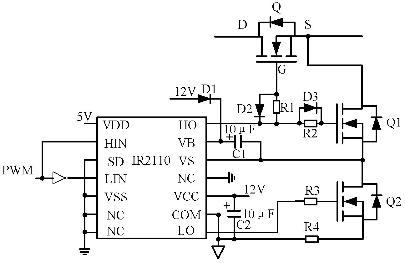
[0023] Such as figure 2 As shown, the present invention provides a switch tube drive circuit based on an integrated drive chip, which is used to provide a drive signal for the switch tube Q. The drive circuit includes an integrated drive chip (in this embodiment, IR2110 is used as an example for illustration), Inverter, diodes D1~D3, resistors R1~R4, electrolytic capacitors C1, C2 and switch tubes Q1, Q2, where the pin HIN of the IR2110 inputs the digital PWM control signal, and the pin LIN is also connected to the aforementioned Digital PWM control signal; pins SD, VSS, and NC are all connected to digital ground, pin VDD is connected to 5V power supply, and pin COM is connected to analog ground; the positive pole of diode D1 is connected to 12V power supply, and the negative pole is connected to pin VB. The pin VB is also connected to th...


PUM


Abstract

The invention discloses a switch tube driving circuit based on an integrated driving chip. The switch tube driving circuit comprises the integrated driving chip, an inverter, three diodes, four resistors, two electrolytic capacitors and two switch tubes, wherein a digital PWM (Pulse-Width Modulation) control signal is input at the high side digital signal input end of the integrated driving chip and a low side digital signal input end is connected with the digital PWM control signal through the inverter; the anode of the first diode is connected with a 12V power supply and the cathode of the first diode is connected with the high side output power supply end of the integrated driving chip, furthermore, the high side output power supply end is connected with the high side output grounding terminal of the integrated driving chip through the first electrolytic capacitor, and the anode of the first electrolytic capacitor is connected with the high side output power supply end; and the grid electrode of a second switch tube is connected with a low side driving signal output end through the third resistor, and the source electrode of the second switch tube is connected with the analog ground through the fourth resistor. The driving circuit has small power consumption and a wide duty ratio range, and digital signals are isolated from analog signals.

Description

technical field [0001] The invention belongs to the field of circuit technology, and in particular refers to a high-side power drive circuit for driving a power converter, which is constructed with a MOSFET integrated drive chip. Background technique [0002] Traditional high-side power switch tube drive circuit, one (can be used with figure 1 (shown) is to use the principle of capacitor boosting to connect a power diode between the source of the high-side power switch and the point where there is always voltage to the ground connected to it, so that the source of the high-side power switch is turned off Due to the reverse non-conduction of the diode, it is disconnected from the point where there is always a voltage to the ground, and at the same time, the negative pole of the boost capacitor is directly grounded through a resistor, so as to complete the charging of the boost capacitor. In this way, the connection resistance and power A large amount of energy will be dissip...

Claims


Application Information

Patent Timeline
Patent Type & Authority Applications(China)
IPC IPC(8): H03K17/687
Inventor 何志强叶永强庄超
Owner HANGZHOU HENGSHENG ELECTRONICS TECH
Why Eureka
Try Eureka