Control device for internal combustion engine

A technology for control devices and internal combustion engines, applied in engine control, electrical control, mechanical equipment, etc., can solve problems such as the difficulty in clearly judging the end of combustion, the inability to obtain the amount of heat generated, and delaying the opening period of the exhaust valve

Inactive Publication Date: 2012-05-02
TOYOTA JIDOSHA KK
View PDF7 Cites 6 Cited by
  • Summary
  • Abstract
  • Description
  • Claims
  • Application Information

AI Technical Summary

Problems solved by technology

[0010] However, in the method that always requires the detection value of the sensor at the end of combustion, no final conclusion on the amount of heat generation can be drawn until the end of combustion
In addition, under operating conditions where the combustion end timing lags behind the usual operating conditions, the combustion end timing may be delayed to the exhaust valve opening timing.
In such a case, there will be uniq

Method used


Image

  • Control device for internal combustion engine
  • Control device for internal combustion engine
  • Control device for internal combustion engine

Examples


Embodiment approach 1

[0057] [Configuration of Embodiment 1]

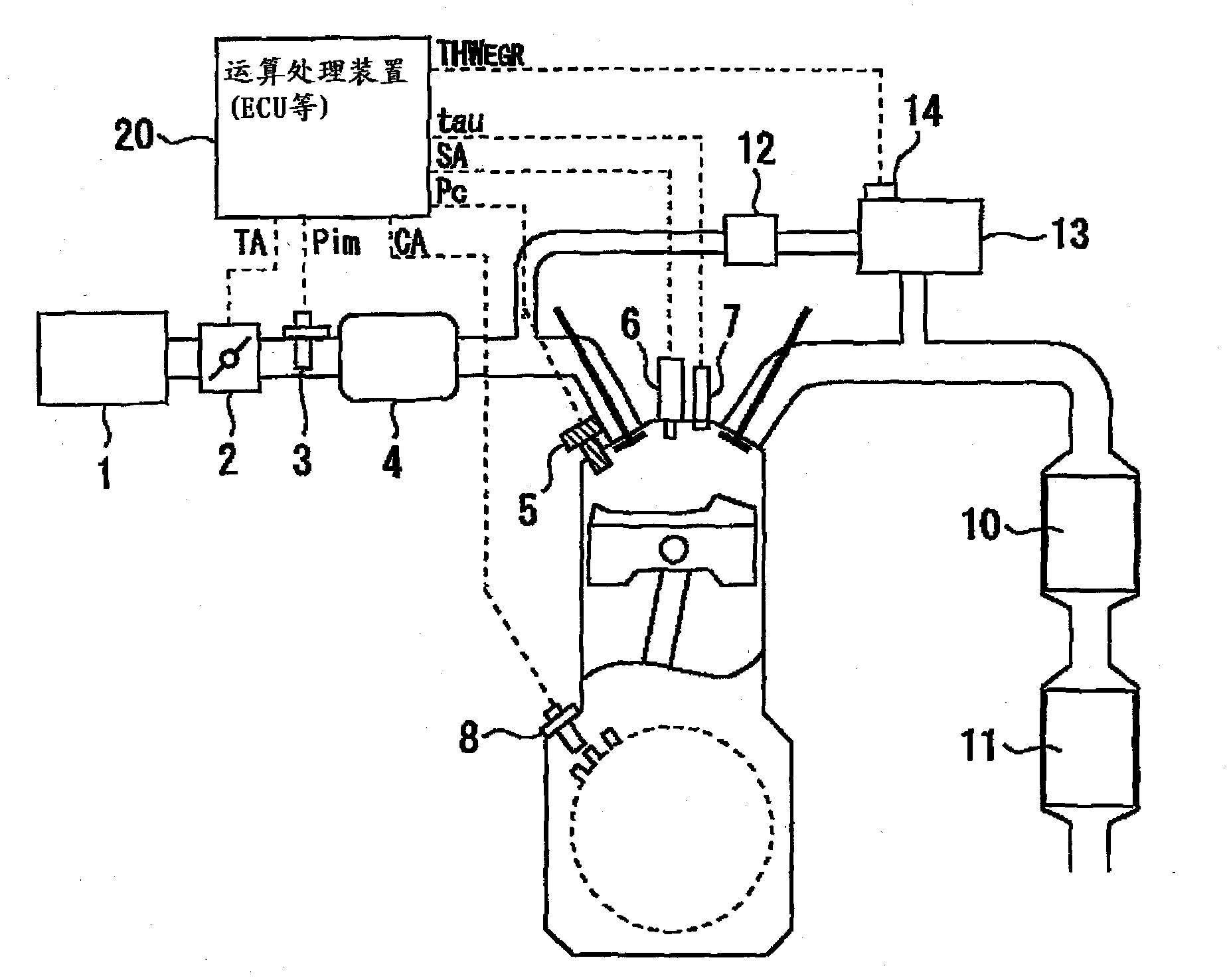
[0058] figure 1 It is a figure which shows the structure of the control apparatus of the internal combustion engine which concerns on Embodiment 1 of this invention. The control device of the present embodiment is suitable for controlling a mobile body such as a vehicle, specifically, an internal combustion engine mounted on an automobile.

[0059] figure 1 is a diagram showing an internal combustion engine (hereinafter simply referred to as an engine) to which the control device of the present embodiment is applied. figure 1 The engine shown is a spark-ignited 4-stroke reciprocating engine with spark plugs 6 . In addition, there is also an in-cylinder direct injection engine including a direct fuel injection injector 7 that directly injects fuel into the cylinder. In addition, the engine to which the present invention is applied is not limited to the in-cylinder direct injection engine of this embodiment. The invention can also be...

Embodiment approach 2

[0120] The hardware structure and software structure of Embodiment 2 can be executed except for the control device related to Embodiment 2 Figure 7 Except for this point of the shown routine, the structure is basically the same as that of the first embodiment. The following uses to avoid repetition, and appropriately omits or simplifies descriptions.

[0121] In large amounts of external EGR and lean burn, retarded combustion can occasionally occur when leaving normal combustion and entering an unstable combustion region. Therefore, in the second embodiment, it is not determined whether or not the catalyst warm-up retardation control is being executed, but θ is always monitored. CA50 , based on ΔPV in the combustion cycle at a retarded angle compared to the specified value k CA50 Estimated calorific value.

[0122] use Figure 7 Specific processing executed in the internal combustion engine control device according to Embodiment 2 will be described. Figure 7 It is a fl...


PUM


Abstract

Disclosed is a control device for an internal combustion engine that can estimate heat production. An arithmetic processing unit (20) can calculate PVK according to a crank angle (theta), and can also calculate the rate of change of PVK (dPVK/d theta). ''The crank angle with the maximum dPVK/d theta value during PVK increase'' means ''50% combustion ratio crank angle'' and for the sake of convenience is also written as ''theta CA50.'' In addition, PVK calculated from theta CA50 is also written as ''PVK CA50.'' Also, for the sake of convenience, the difference between PVK at the time that combustion starts (zero, as in figures 3 and 4 of the present embodiment) and PVK CA50 is written as delta PVK CA50. The doubled value of delta PVK CA50 equals total heat production (Q).

Description

technical field [0001] The invention relates to a control device for an internal combustion engine. Background technique [0002] Conventionally, for example, as disclosed in Japanese Patent Application Laid-Open No. 2006-144643, there is known a technique for obtaining various information on the calorific value during combustion of an internal combustion engine by calculation. The aforementioned gazette specifically discloses a technique of calculating a calorific value immediately after combustion using an output value of a cylinder internal pressure sensor, and calculating a combustion air-fuel ratio based on the calorific value. [0003] prior art literature [0004] patent documents [0005] Patent Document 1: Japanese Patent Document Laid-Open No. 2006-144643; [0006] Patent Document 2: Japanese Patent Document Laid-Open No. 2007-120392; [0007] Patent Document 3: Japanese Patent Application Laid-Open No. 2007-113396. [0008] There is known a technique for obta...

Claims


Application Information

Patent Timeline
IPC IPC(8): F02D45/00
CPCF02D35/028F02D45/00F02D41/0255F02D35/024F02D41/1498
Inventor 安田宏通铃木裕介田中聪一郎
Owner TOYOTA JIDOSHA KK
Why Eureka
Try Eureka