Power generating apparatus, power generating system, and wireless power transmitting apparatus

一种发电装置、天线的技术,应用在电路装置、电磁波系统、电池电路装置等方向,能够解决难以维持能量输出等问题

Active Publication Date: 2012-05-02
PANASONIC INTPROP MANAGEMENT CO LTD
View PDF11 Cites 28 Cited by
  • Summary
  • Abstract
  • Description
  • Claims
  • Application Information

AI Technical Summary

Problems solved by technology

Under such environmental changes, it is difficult to maintain a stable energy output

Method used


Image

  • Power generating apparatus, power generating system, and wireless power transmitting apparatus
  • Power generating apparatus, power generating system, and wireless power transmitting apparatus
  • Power generating apparatus, power generating system, and wireless power transmitting apparatus

Examples


no. 1 approach

[0107] First, refer to Figure 5 ~ Figure 21 , the first embodiment of the power generating device of the present invention will be described. exist Figure 5 ~ Figure 21 in, for Figure 1~4 The components corresponding to the components shown are denoted by the same reference signs.

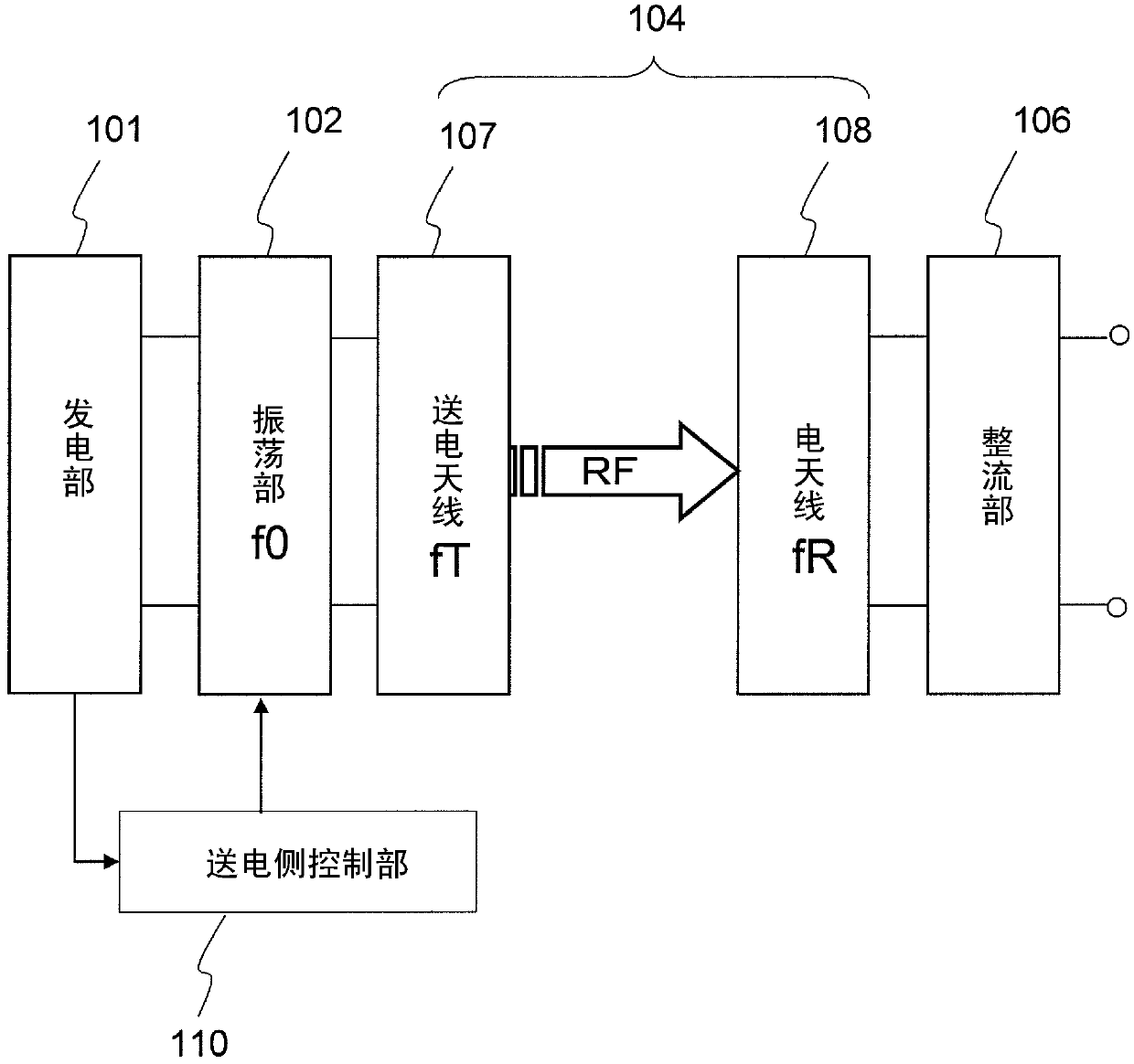
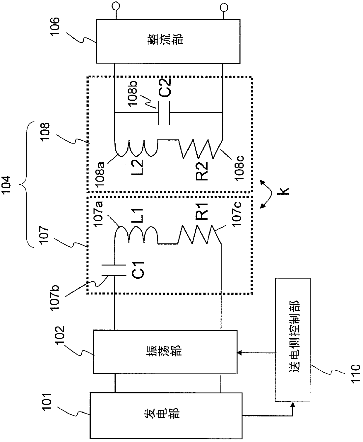
[0108] Figure 5 It is a schematic configuration diagram of the power generator of the present embodiment. As shown in the figure, the power generating device of this embodiment includes a power generating unit 101, an oscillating unit 102, an oscillating unit impedance matching unit 103, a wireless transmission unit 104, a rectifying unit impedance matching unit 105, and a rectifying unit 106, which are connected in series. In addition, a load 113 is connected to a subsequent stage of the rectification unit 106 . The power generation device further includes: an output current voltage measurement unit 109, which measures the output current and output voltage of the power generation unit 101...

Embodiment approach 2

[0213] Next, refer to Figure 22 Embodiments of the power generation system of the present invention will be described. Figure 22 It is a block diagram of the power generation system in this embodiment. exist Figure 22 Herein, the same reference numerals are attached to the same components as those of the power generator in the above-mentioned embodiment, and detailed description thereof will be omitted.

[0214] Figure 22 The power generation system includes a plurality of power generation devices 131a, 131b, . . . , 131n connected in parallel. Although the power generating devices 131a to 131n in this embodiment are all the power generating devices of Embodiment 1, at least two power generating devices connected in parallel need only be the power generating devices of the present invention in order to obtain the effect of the present invention.

[0215] Each power generating device 131a to 131n includes a power generating unit 101, an oscillating unit 102, an oscillat...


PUM


Abstract

Disclosed is a power generating apparatus which is provided with: a power generating unit (101), which outputs direct-current energy; an oscillating unit (102), which converts the direct-current energy into RF energy at a frequency (f0); a power transmitting antenna (107), which transmits the RF energy; a power receiving antenna (108), which receives at least a part of the RF energy transmitted from the power transmitting antenna (107); and a power transmission side control unit (110), which matches the input impedance of the power generating unit (101) with the output impedance of the oscillating unit (102) by changing the input impedance of the oscillating unit (102) corresponding to changes of the output impedance of the power generating unit (101). The power transmitting antenna (107) is a serial resonance circuit, and the power receiving antenna (108) is a parallel resonance circuit. The resonance frequency (fT) of the power transmitting antenna (107) and the resonance frequency (fR) of the power receiving antenna (108) are set equal to the frequency (f0) of the RF energy.

Description

technical field [0001] The present invention relates to a power generation device, a power generation system, and a wireless power transmission device that supply energy via space. Background technique [0002] From the standpoint of depletion of natural resources and countermeasures against the greenhouse effect, interest in solar power generation that does not emit carbon dioxide has been escalating. In recent years, factories that generate large amounts of power by laying a large number of solar power generation elements (solar cells: hereinafter sometimes referred to as "unit cells") over a large area have gradually become a reality. Although solar power generation devices for home use have been mainly installed on roofs and the like of buildings until now, studies have begun to place them on walls of buildings. [0003] In a general solar power generation system, a plurality of unit cells are arranged in a metal frame, and a "solar cell module" is used in which the uni...

Claims


Application Information

Patent Timeline
Patent Type & Authority Applications(China)
IPC IPC(8): H02J17/00
CPCH02J7/025H02J17/00H02S10/00H02J50/12H02J50/20H02J7/00034Y02E10/50H02J50/80
Inventor 山本浩司菅野浩
Owner PANASONIC INTPROP MANAGEMENT CO LTD
Why Eureka
Try Eureka