Coaxially-packaged DFB laser transmitter with refrigeration function

A technology of laser emitters and packaging tapes, which is applied in the direction of lasers, phonon exciters, laser components, etc., can solve the problems of difficult to achieve wavelength division multiplexing long-distance transmission, no temperature control, large packaging size, etc., to achieve suppression Chirp effect, precise temperature control, low cost effect

Inactive Publication Date: 2015-07-29
DALIAN CANGLONG OPTOELECTRONICS TECH
View PDF11 Cites 8 Cited by
  • Summary
  • Abstract
  • Description
  • Claims
  • Application Information

AI Technical Summary

Problems solved by technology

The DFB laser has a simple structure and is easy to implement, but the modulation current will cause a change in the refractive index of the active layer, resulting in the modulation of the phase of the light, thereby broadening the operating frequency, and most of the current DFB lasers do not have temperature control, which is prone to chirp (Chirp) effect, it is difficult to achieve wavelength division multiplexing to achieve long-distance transmission
Part of the DFB laser is packaged into a temperature-controlled laser. The utility model patent No. 200420046800.9 discloses a DFB laser component. The laser is equipped with a thermoelectric cooler to suppress the chirp effect. However, because it is packaged in a shell, Therefore, there are disadvantages of large package size and high cost
The transmission performance of electroabsorption modulated lasers (EA modulated lasers) is better than that of DFB lasers, but due to the limitation of EA chips, the cost has always been relatively high
EML laser chips have been monopolized by foreign chip companies and are expensive

Method used


Image

  • Coaxially-packaged DFB laser transmitter with refrigeration function
  • Coaxially-packaged DFB laser transmitter with refrigeration function
  • Coaxially-packaged DFB laser transmitter with refrigeration function

Examples


Embodiment Construction

[0016] The present invention will be further described below in conjunction with specific examples.

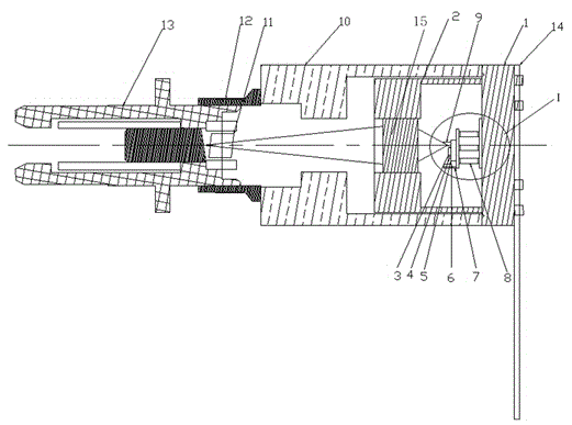
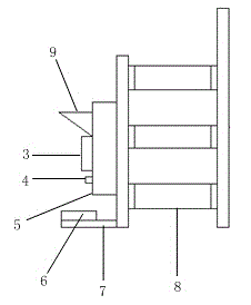
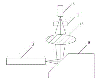
[0017] Such as figure 1 , 2 As shown, the present invention adopts a TO-8 package structure, mainly including a tube base 1, a tube cap 2, a DFB laser chip 3, a thermistor 4, a laser chip heat sink 5, a backlight detection chip 6, a detection chip heat sink 7, a thermoelectric Refrigerator 8, 45° full reflection film 9, housing 10, optical isolator 11, metal sleeve 12, adapter 13, soft belt 14 and lens 15. The cavity of the laser transmitter is composed of a tube base 1, a housing 10 and an adapter 13, and the tube base 1 needs to meet the 10G communication transmission rate. The DFB laser chip 3 is mounted on the laser chip heat sink 5 through gold selenium solder, and the backlight detection chip 6 is mounted on the detection chip heat sink 7 through epoxy glue. The tube base 1, tube cap 2, optical isolator 11, adapter 13 and 45° full reflection film 9 in the cavity are i...


PUM


Abstract

The invention belongs to optical communication devices, particularly relates to a laser transmitter, and provides a coaxially-packaged DFB laser transmitter with a refrigeration function. The coaxially-packaged DFB laser transmitter comprises a cavity, a DFB laser chip mounted on a laser chip heat sink and a backlight detection chip mounted on a detection chip heat sink are arranged in the cavity, a TO package structure is adopted, a tube seat, a tube cap, an optical isolator, an adaptor, a lens and a 45-degree total-reflection sheet are coaxially packaged in the cavity, one side of a thermoelectric refrigerating unit is mounted under the laser chip heat sink, and the other side of the same is mounted on the tube seat. The TO coaxial package structure is adopted, the 45-degree total-reflection sheet is adopted to effectively solve the problem of a light path structure, and the thermoelectric refrigerating unit is arranged inside the DFB laser transmitter to accurately control working temperature of the laser transmitter. The coaxially-packaged DFB laser transmitter has the advantages of small size, low cost, stable output wavelength and the like, and high-speed long-distance transmission of laser is realized favorably.

Description

technical field [0001] The invention belongs to optical communication devices, in particular to laser emitters. Background technique [0002] Semiconductor laser is a light source device in optical fiber communication, which has the characteristics of direct electro-optic conversion, fast response, small size, and long life. There are two main modulation methods of semiconductor laser signals: direct modulation laser (DFB laser) and external modulation laser (EML laser). Directly modulated laser is to modulate the output of laser by changing the input current. DFB laser has become the main light source in optical fiber communication due to its characteristics of dynamic single mode and fast response. The DFB laser has a simple structure and is easy to implement, but the modulation current will cause the change of the refractive index of the active layer, resulting in the modulation of the phase of the light, thus broadening the operating frequency, and most of the current D...

Claims


Application Information

Patent Timeline
Patent Type & Authority Applications(China)
IPC IPC(8): H01S5/12H01S5/024
Inventor 张彩徐泽池张博
Owner DALIAN CANGLONG OPTOELECTRONICS TECH
Why Eureka
Try Eureka