
Method for improving heat transfer coefficient of heat exchanger by utilizing medium shear force

A heat transfer coefficient and heat exchanger technology, which is applied in heat transfer modification, heat exchange equipment, lighting and heating equipment, etc., can solve the problems of high material requirements, difficult cleaning, complex structure, etc., to improve heat transfer coefficient, Improve heat transfer conditions and facilitate operation and maintenance

Inactive Publication Date: 2012-05-09
姚光纯
View PDF8 Cites 5 Cited by
  • Summary
  • Abstract
  • Description
  • Claims
  • Application Information

AI Technical Summary

Problems solved by technology

So far, how to improve the heat transfer coefficient of the heat exchanger has been studied by changing the fluid state, but most of them improve the flow state of the fluid in the heat exchanger by changing the structure of the partition heat exchanger itself. , such as perforated diaphragm tubes, spiral flat tubes, and variable-section tubes mentioned in the research progress of shell-and-tube heat exchangers, CN101566437A made the tubes into a composite casing double helix structure, and added a helical agitator in CN101226041A, It breaks the temperature gradient propagation mode during laminar flow, but their structures are relatively complicated, and there are also CN2802425Y that changes the fluid flow mode of the shell side, or changes the form of the shell side baffle
These have more or less improved the heat transfer efficiency of the heat exchanger, but there are various problems, such as high requirements for materials, difficult cleaning, complex structure

Method used


Image

  • Method for improving heat transfer coefficient of heat exchanger by utilizing medium shear force
  • Method for improving heat transfer coefficient of heat exchanger by utilizing medium shear force
  • Method for improving heat transfer coefficient of heat exchanger by utilizing medium shear force

Examples


Embodiment Construction

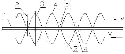
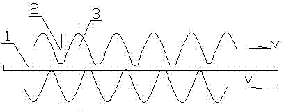
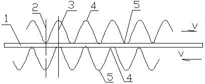
[0011] exist figure 1 , figure 2 , image 3 and Figure 4 In, a pulsation generator is set before the inlet of the heat exchanger (partition wall type), such as figure 1 As shown, the pulsation generator causes the fluid (medium) on both sides of the heat exchange surface 1 in the entire flow channel of the heat exchanger to generate a pulsation flow in which the direction of pulsation is opposite but the peak 4 and the trough 5 correspond to the same point on the heat exchange surface. The fluid medium on the upper side pulsates to the right, the fluid medium on the lower side of the heat exchange surface pulsates to the left, the trough 5 of the fluid pulsation on the upper side of the heat exchange surface and the peak 4 of the fluid pulsation on the lower side are on the vertical plane 2 of point A on the heat exchange surface Correspondingly, the peak 4 of the upper fluid pulsation on the heat exchange surface and the trough 5 of the lower fluid pulsation correspond t...


PUM


Abstract

The invention discloses a method for improving the heat transfer coefficient of a heat exchanger by utilizing medium shear force, which is characterized in that: a pulsating generator capable of allowing fluids in the whole runner of the heat exchanger to generate pulsating flow is arranged in front of an inlet of the heat exchanger; by adjusting the pulse generator, the pulsating frequencies of two fluids change, and pulsating waveforms of the fluids at the two sides of a heat exchange surface (1) are mutually staggered until peaks (4) and peaks, and troughs (5) and troughs respectively and homogeneously correspond to each other at one point on the heat exchange surface, so that the fluids pulsate to generate shear force; and the heat exchange surface vibrates under the action of the shear force, the vibration of the heat exchange surface damages a fluid stagnant layer and strips a dirt layer, and the heat resistance value of the fluids is reduced, thereby the heat transfer coefficient of a dividing wall type heat exchanger is improved. According to the method for improving the heat transfer coefficient of the heat exchanger, the heat exchange surface can vibrate under the action of the shear force without changing the structure of the heat exchanger by only needing to adjust the pulsating generator appropriately, therefore, the heat transfer coefficient of the heat exchanger is improved, the structure is simple, the applicability is strong, and the operation and maintenance are convenient.

Description

technical field [0001] The invention relates to a method for improving the heat transfer coefficient of a heat exchanger by using medium (fluid) shear force. Background technique [0002] Heat exchanger is an energy-saving equipment that realizes heat transfer between materials, and is widely used in petroleum, chemical, metallurgy, electric power, light industry, food and other industries. In various devices in oil refining and chemical industries, heat exchangers account for about 40% of the total equipment and 30%-45% of the total investment. In recent years, with the development of energy-saving technology, the application fields of heat exchangers have been continuously expanded, which has brought significant economic benefits. At present, more than 90% of the heat exchangers are partition wall heat exchangers. From the essence of heat transfer, it is fundamental to improve the heat transfer coefficient. Therefore, for a long time, people hope that the partition wall h...

Claims


Application Information

Patent Timeline
Patent Type & Authority Applications(China)
IPC IPC(8): F28F13/10
Inventor 姚光纯徐德懿
Owner 姚光纯
Learn More