System and method for measuring surface energy flux density
An energy flow density and measurement system technology, which is applied in the field of the surface energy flow density measurement system of the receiving surface, can solve the problems such as the measurement of the energy flow density not applicable to the large-size receiving surface, the high manufacturing cost and the difficulty, and achieves low cost, The effect of improving precision, improving accuracy
- Summary
- Abstract
- Description
- Claims
- Application Information
AI Technical Summary
Problems solved by technology
Method used
Image

Examples
Embodiment 1
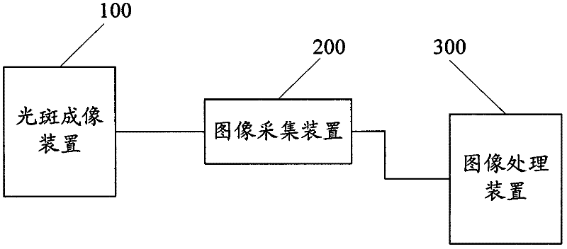
[0042] A method for measuring surface energy flux density, used to indirectly measure the surface energy flux density of a receiving surface, including the following steps:
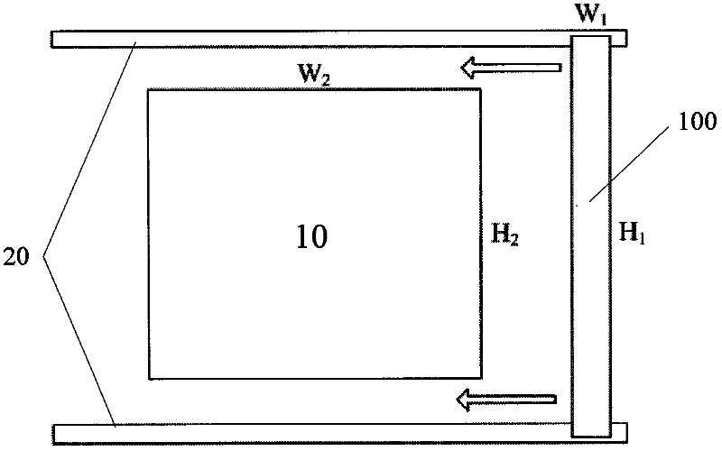
[0043] (1) Install two parallel guide rails 20 (motion assistance mechanism) along the upper and lower ends of the receiving surface 10, such as figure 2 As shown, the light spot imaging device 100 is a long strip, and the two ends are respectively connected to two guide rails 20 and slide along the receiving surface through the guide rails 20 (the light spot imaging device is located in front of the receiving surface), and the movement track of the light spot imaging device 100 covers the entire receiving surface 10.
[0044] The width and height of the spot imaging device are determined according to the actual size of the receiving surface. For ease of installation, the height of the spot imaging device 100 is H 1 Slightly larger than the height H of the receiving surface 10 2 , The width W of the spot imagi...
Embodiment 2
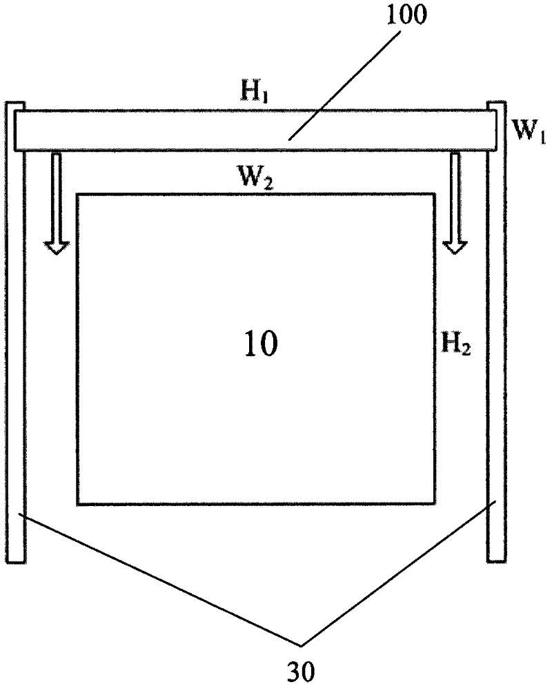
[0072] Such as image 3 As shown, two parallel guide rails 30 are vertically arranged along the left and right ends of the receiving surface 10, the spot imaging device 100 is a long strip, and the two ends are respectively connected to the two guide rails 30 and move up and down along the receiving surface through the guide rails 30 (light spot The imaging device is located in front of the receiving surface), and the movement track of the light spot imaging device 100 covers the entire receiving surface 10. The width and height of the light spot imaging device and the receiving surface, the length of the guide rail, the moving speed of the light spot imaging device and the shooting speed of the image acquisition device are the same as in the first embodiment.
Embodiment 3
[0074] Such as Figure 4 As shown, a rotating shaft 40 is fixedly installed around the receiving surface 10 (the rotating shaft is arranged at any suitable position around the receiving surface or in the receiving surface area. The installation position is not limited and can be freely selected according to needs to ensure that the light spot imaging device rotates track coverage The entire receiving surface), one end of the spot imaging device 100 is pivotally connected to the rotating shaft 40, and rotates around the rotating shaft 40 along the receiving surface 10 (the spot imaging device is located in front of the receiving surface). The shape and size of the spot imaging device 100 ensure that its movement track covers the entire Receiving surface 10 is enough. The rotational angular velocity of the light spot imaging device is π / 6 radians / second, and the shooting speed of the image acquisition device is 20 frames / second (the rotational angular velocity of the light spot im...
PUM
 Abstract
Description
Claims
Application Information
 - R&D
- Intellectual Property
- Life Sciences
- Materials
- Tech Scout
- Unparalleled Data Quality
- Higher Quality Content
- 60% Fewer Hallucinations
Browse by: Latest US Patents, China's latest patents, Technical Efficacy Thesaurus, Application Domain, Technology Topic, Popular Technical Reports.
© 2025 PatSnap. All rights reserved.Legal|Privacy policy|Modern Slavery Act Transparency Statement|Sitemap|About US| Contact US: help@patsnap.com