Tilting-type automatic molten metal pouring method, tilting control system, and storage medium having tilting control program stored therein

An automatic pouring and tilting technology, which is applied in the control of molten metal pouring from the ladle, manufacturing tools, equipment for supplying molten metal, etc., can solve the problems of long operating time, response characteristics, measurement noise interference, and real-time computing load major issues

Active Publication Date: 2012-05-09
SINTOKOGIO LTD +1
View PDF7 Cites 22 Cited by
  • Summary
  • Abstract
  • Description
  • Claims
  • Application Information

AI Technical Summary

Problems solved by technology

Therefore, the action time of the back tilt becomes longer
In addition, since the influence of the change in melt flow due to the tilt angle of the ladle is not considered, there is a problem that the accuracy of the melt outflow weight decreases due to the tilt angle of the ladle
[0011] In addition, in Patent Document 3, the shape of the ladle is limited to a sector
In addition, since the state prediction formula based on repeated calculations is used, there is a problem that the real-time calculation load of the controller is large.
[0012] In addition, the pouring methods described in Patent Document 1, Patent Document 2, and Patent Document 3 also have the problem that the accuracy of the outflow weight is greatly affected by the response characteristics of the load cell used to measure the outflow weight of the melt and the interference of measurement noise.

Method used

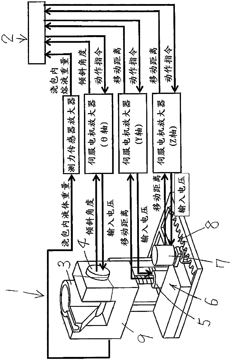
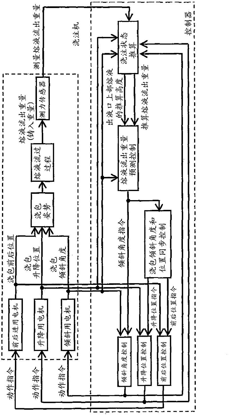

Image

  • Tilting-type automatic molten metal pouring method, tilting control system, and storage medium having tilting control program stored therein
  • Tilting-type automatic molten metal pouring method, tilting control system, and storage medium having tilting control program stored therein
  • Tilting-type automatic molten metal pouring method, tilting control system, and storage medium having tilting control program stored therein

Examples


Embodiment

[0125] The inner shape and outlet shape of the ladle used in the experiment are shown in Figure 9 middle.

[0126] If according to Figure 9 The shape of the ladle is used to obtain the volume V of the melt at the lower part of the ladle outlet for the inclination angle q s , melt surface area A, then as Figure 10 . Figure 10 The relationship between the melt volume at the lower part of the ladle outlet and the melt surface area shown can be obtained by numerical integration. Alternatively, it may be obtained by using CAD software.

[0127] Here, f of equation (37) vs yes Figure 10 The inclination angle q of (a) and the melt volume V at the lower part of the ladle outlet s The inverse mapping of the relation. And, the melt height h at the liquid outlet and the pouring flow rate q when the flow coefficient is 1 f The relationship between Figure 11 shown. Figure 11 The relationship can be obtained by formula (5). In addition, the flow coefficient is set to c=0....


PUM

PropertyMeasurementUnit
Gain coefficientaaaaaaaaaa

Abstract

A method of automatically pouring molten metal from a ladle into a mold by tilting the ladle. In the method, the height of molten metal located above a molten metal outlet and the weight of molten metal flowing out of the ladle are estimated using an expanded Kalman filter on the basis of: the weight of the molten metal flowing out of the ladle, said weight being measured using a load cell; the voltage inputted to a servo motor; the angle of tilt of the ladle measured by a rotary encoder; and the position of the ladle in the lifting and lowering direction thereof. The sum of the weight of the molten metal flowing out of the ladle when the ladle is tilted rearward, said weight being estimated from the angle of tilt of the ladle and the height of the molten metal located above the molten metal outlet estimated by the expanded Kalman filter, and the weight of the molten metal flowing out of the ladle estimated by the expanded Kalman filter are estimated as the final weight of outflowing molten metal. The estimated final weight of outflowing molten metal is determined whether or not to be greater than or equal to a specific weight of outflow, and the operation of rearward tilting of the ladle is started on the basis of the result of the determination.

Description

technical field [0001] The present invention relates to a tilting type automatic pouring method for automatically pouring from a ladle to a mold by tilting a ladle holding a molten liquid, a system for controlling the tilt of the ladle, and a storage medium storing the control program thereof, more specifically In other words, it involves the use of a servo motor controlled by a computer preset with a program for performing the pouring process, so that the ladle with a liquid outlet of a predetermined shape is tilted forward and then tilted backward, thereby pouring into the mold. A ladle tilting automatic pouring method for molten liquid in a ladle, a tilt control system for a ladle, and a storage medium storing a tilt control program for a ladle. Background technique [0002] Conventionally, there are methods disclosed in Patent Documents 1, 2, and 3 as representative inclined automatic pouring methods. [0003] In the method described in Patent Document 1, the ladle is r...

Claims


Application Information

Patent Timeline
Patent Type & Authority Applications(China)
IPC IPC(8): B22D41/06B22D39/04B22D46/00
CPCB22D41/06B22D39/04B22D37/00B22D46/00
Inventor 寺嶋一彦野田善之铃木薪雄牧野泰育太田和弘
Owner SINTOKOGIO LTD
Why Eureka
Try Eureka