Refrigerator equipped with vacuum insulation material

A technology of vacuum insulation materials and refrigerators, which can be used in home appliances, mechanical equipment, heat exchange equipment, etc., and can solve the problems of not being able to give full play to the thermal insulation performance, promoting the thermal bridge of the cladding material and failing to obtain the predetermined effect, etc., to achieve the purpose of suppressing thermal insulation Deterioration of performance, reduction of man-hours for assembly work, effects of uniform load

Inactive Publication Date: 2012-05-09
HITACHI APPLIANCES INC
View PDF6 Cites 12 Cited by
  • Summary
  • Abstract
  • Description
  • Claims
  • Application Information

AI Technical Summary

Problems solved by technology

[0004] As the existing technology, generally considering workability, etc., for example, vacuum insulation materials are often placed on the flat part of the outer box side of the refrigerator box, but there are also thermal bridges of the coating materials that are unique to vacuum insulation materials.

Method used


Image

  • Refrigerator equipped with vacuum insulation material
  • Refrigerator equipped with vacuum insulation material
  • Refrigerator equipped with vacuum insulation material

Examples


Example

[0040] The first embodiment

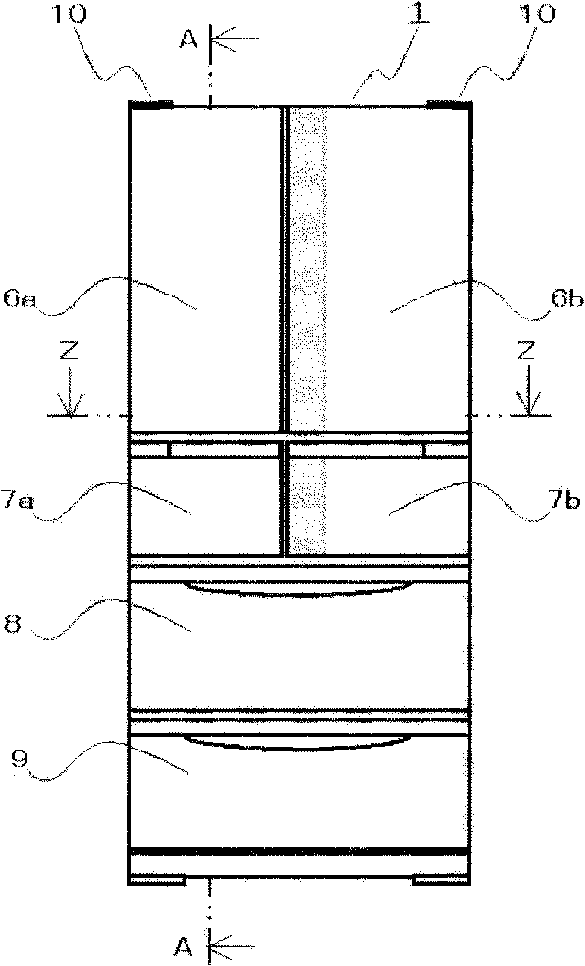
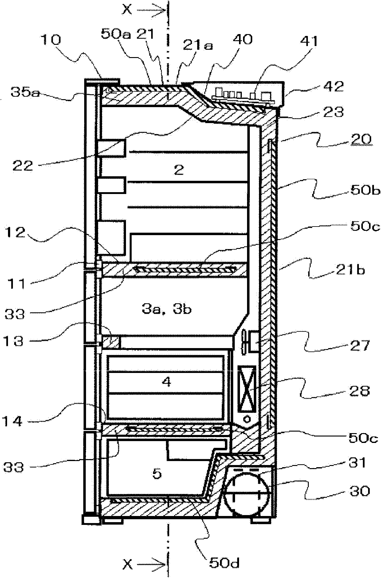
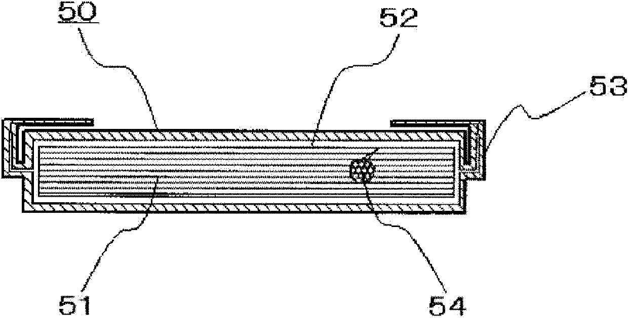
[0041] Regarding the refrigerator provided with the vacuum insulation material according to the first embodiment of the present invention, refer to Figure 1 ~ Figure 7 Be explained. figure 1 It is a front view of the external appearance of the refrigerator provided with the vacuum insulation material concerning the 1st Embodiment of this invention. figure 2 It is a vertical cross-sectional view of a refrigerator equipped with a vacuum insulation material according to the first embodiment. figure 1 A cross-sectional view of line A-A. image 3 It is a cross-sectional view of the vacuum insulation material used in the first embodiment.

[0042] In addition, Figure 4 It is a vertical cross-sectional view of a refrigerator equipped with a vacuum insulation material according to the first embodiment. figure 2 Sectional view of the X-X line. Figure 5 It is a cross-sectional view of a refrigerator equipped with a vacuum insulation material according to th...

Example

[0071] Second embodiment

[0072] Next, refer to Figure 8 The structure of the separator in the refrigerator provided with the vacuum insulation material according to the second embodiment of the present invention will be described. Figure 8 It is a figure which shows the arrangement|positioning of the separator with respect to an outer box concerning 2nd Embodiment, and the foaming direction of foamed polyurethane. In the second embodiment, due to figure 1 , image 3 , Figure 4 , Figure 5 and Figure 7 The structure of the refrigerator provided with the vacuum insulation material according to the first embodiment described is the same, so this structure is used.

[0073] in Figure 8 In the second embodiment, since the spacer 71 used in the second embodiment is formed into a predetermined shape with the same material as the foamed polyurethane 23 with a molding die not shown in the figure, it has the same function as the spacer 70 of the first embodiment. In order to make the ...

Example

[0084] The third embodiment

[0085] Next, refer to Picture 11 and Picture 12 The related structure and arrangement structure of the shape of the spacer and the heat dissipation pipe according to the third embodiment will be described below. Such as Picture 11 As shown in (a), the spacer 77 used in the third embodiment is provided with a relief groove so that the heat dissipation pipe 90 does not abut on the spacer 70 of the first embodiment. Such as Picture 11 As shown in (b), a relief groove 77c for the heat pipe 90 is provided on the joint surface 77b so that a spacer 77 can be provided on the inner surface of the outer box 21e on the projection surface of the heat pipe 90 fixed by the aluminum tape 91 . Regarding the groove 77c, the width and height are set to be larger than the diameter of the heat dissipation pipe 90 so that the foamed polyurethane 23 flows between the heat dissipation pipe 23 and the groove 77c and fills it. Regarding the radiating pipe 90, as shown ...


PUM

PropertyMeasurementUnit
Thicknessaaaaaaaaaa

Abstract

Provided is a refrigerator wherein a spacer and a supporting member are arranged between a vacuum insulation material and the outer box and the inner box, respectively, so that the vacuum insulation material is not peeled by the foaming pressure of urethane foam and a portion not filled with urethane foam does not occur. Since a continuous plane is employed as the adhesion plane of a vacuum insulation material (50e) and the outer box (21e) in a spacer (70) when the vacuum insulation material (50e) is arranged, adhesion area can be increased, the spacer (70), the vacuum insulation material (50e) and the outer box (21e) can be bonded strongly, and application work of adhesive or sticking work is facilitated because the adhesion plane is a continuous plane. Furthermore, the vacuum insulation material (50e) is not peeled by foaming pressure because such a structure as the vacuum insulation material (50e) is sandwiched by the spacer (70) and a supporting member (80) can be taken by arranging the supporting member (80) on the inner box side or on the surface of the vacuum insulation material on the inner box side.

Description

technical field [0001] The invention relates to a refrigerator, in particular to the shape of a vacuum heat insulating material, and the related structures of the vacuum heat insulating material, an outer box and an inner box. Background technique [0002] In recent years, refrigerators have been required to save energy from the viewpoint of global environment protection such as prevention of global warming. In addition, as a recent social background, there is a tendency of double-employment and small households. Therefore, due to the increase in households that use weekends and rest days to collectively purchase food materials, the demand for larger refrigerators is increasing year by year. [0003] In order to save energy, conventional refrigerators have been sold by using rigid polyurethane foam as the insulation material of the refrigerator body and vacuum insulation material to greatly improve the insulation performance. Vacuum insulation has more than 10 times the the...

Claims


Application Information

Patent Timeline
IPC IPC(8): F25D23/06
CPCF25D2201/14F25D23/062F16L59/06F25D23/06
Inventor 越后屋恒荒木邦成井关崇石渡宽人鹤贺俊光新井佑志
Owner HITACHI APPLIANCES INC
Why Eureka
Try Eureka