

Vacuum heat insulating material and machine using the same vacuum heat insulation material
A technology of vacuum insulation materials and machines, which can be used in mechanical equipment, thin material processing, heat exchange equipment, etc., and can solve problems such as insufficient
- Summary
- Abstract
- Description
- Claims
- Application Information
AI Technical Summary
Problems solved by technology
Method used
Image

Examples
Embodiment approach 1
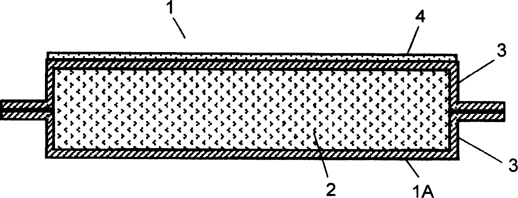
[0025] First, the formation of the radiant heat conduction suppressing portion 4 with a coating film containing an infrared reflection component will be described. Hereinafter, regarding samples 1 to 4, various coating films were formed as radiant heat conduction suppressing portions 4 on the surface of the outer covering material 3 of the vacuum heat insulating material main body 1A. In addition, the heat insulating performance of the vacuum heat insulating material 1 was evaluated by measuring the temperature of the surface on the low temperature side when heat of 150° C. was applied to the surface on the high temperature side using a halogen heater.
[0026] Sample 1 contains a leafing aluminum flake pigment which is a metal powder as an infrared reflection component, and forms a coating film containing an epoxy resin as a resin component. Sample 2 contained a leafing type aluminum flake pigment in the same manner as Sample 1, and formed a coating film of polychlorotrifluor...
Embodiment approach 2
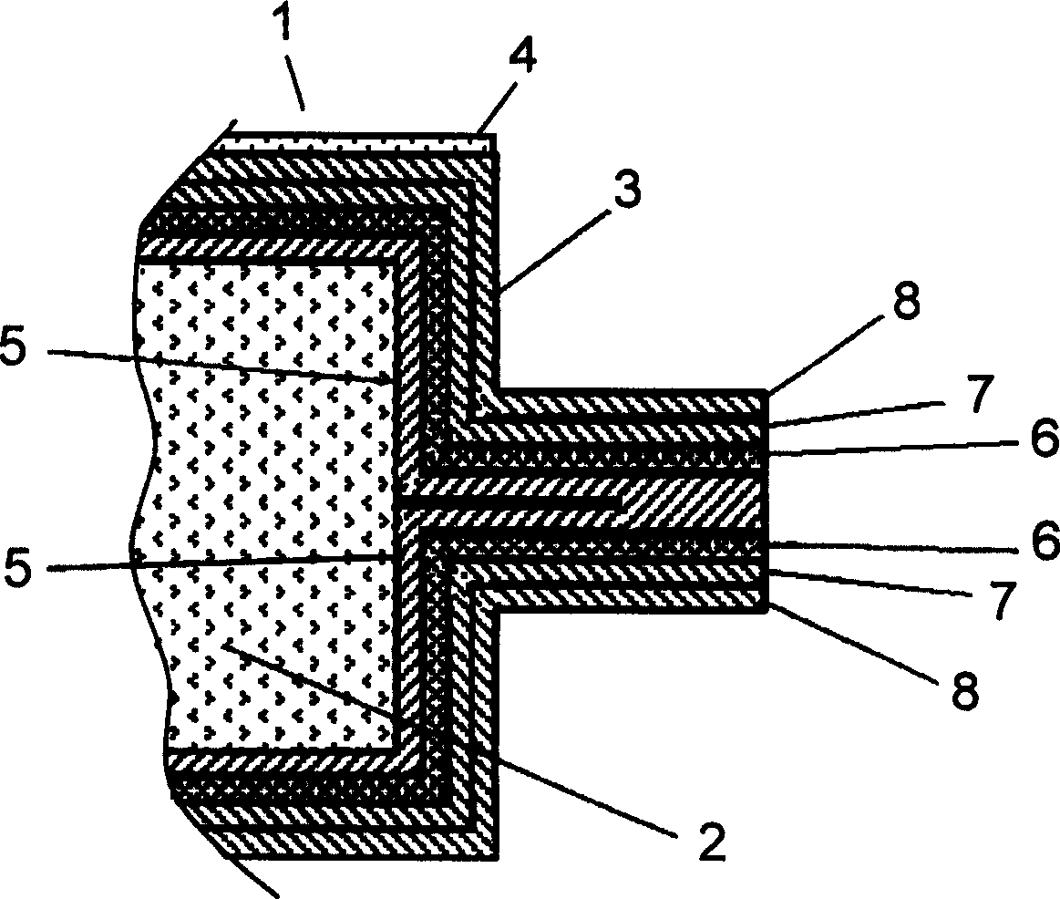
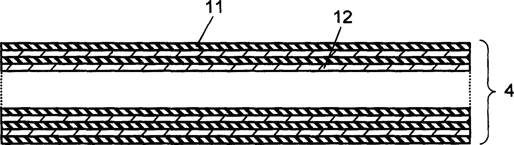
[0039] Next, the formation of the radiant heat suppressing portion 4 using a laminate of inorganic material thin films having different refractive indices will be described. Basic configuration of vacuum insulation material and the first embodiment figure 1 , 2 same.
[0040] image 3 It is a sectional view of the radiation heat conduction suppressing part 4 in this embodiment. The radiant heat conduction suppressing portion 4 in this embodiment is a radiant heat suppressing film in which four first inorganic thin films 11 made of magnesium fluoride and second inorganic thin films 12 made of calcium fluoride and having different refractive indices are alternately laminated in four layers. .
[0041] When inorganic material thin films with different refractive indices are alternately laminated with a thickness of 1 / 4 of a specific wavelength, the reflection wavefronts from the boundary surfaces of each layer overlap additively, and far-infrared rays are reflected wavelength...
Embodiment approach 3
[0048] Next, the formation of the radiative heat conduction suppressing portion 4 using a metal thin film will be described. Basic configuration of vacuum insulation material and the first embodiment figure 1 , figure 2 same.
[0049] In this embodiment, the metal thin film forming the radiant heat conduction suppressing portion 4 is a thinned metal foil or a laminated foil metal thin film. or as Figure 4 As shown in the cross-sectional view of the resin substrate 14, it includes a thin-layered metal film 13 or a laminate thereof formed on the surface of the resin substrate 14 by evaporation, sputtering, electrolytic deposition, etc., or is composed of an inorganic substance or a semiconductor. A laminate in which the thin layers are stacked together.
[0050] Figure 5 It is a characteristic diagram showing the relationship between black body radiation energy and wavelength at 150°C, Image 6 It is a characteristic diagram showing the reflectance when light is project...
PUM
| Property | Measurement | Unit |
|---|---|---|
| melting point | aaaaa | aaaaa |
| melting point | aaaaa | aaaaa |
| melting point | aaaaa | aaaaa |
Abstract
Description
Claims
Application Information